When mounting M101/M102 on the backside of the PCB, sandwiched between the PCB and the heat sink, should there be any thermal insulation between the PCB and mosfet? I assume it’s not necessary but please correct me if I’m wrong.
I will definitely use insulating thermal pads between the mosfets and the heatsink.
I will definitely use insulating thermal pads between the mosfets and the heatsink.

First power-up tests didn't go so well 😳
Just doing the dim-bulb test before attempting bias and offset adjustment. Potentiometers are set to halfway (I counted 30 turns from CW clicks to CCW clicks and then did 15 CW turns from the CCW click side).
Left Channel:
The first time power was applied the bulb went to half brightness (normal), then went down to 1/4 brightness. I smelled burning and saw a little smoke coming up from the PCB somewhere near the corner where the input is. Removed power and found that T202 was hottish.
Pulled the board out of the chassis and checked solder joints. Reinstalled the caps to make sure I'd soldered on the topside since I'd installed the cap bodies almost against the PCB, making it impossible to see solder joint. Now I'm sure all components are soldered on top and bottom.
Tried dim-bulb again and while the light acts normal (goes to half brightness then fades out), T202 is still getting hot after 10 seconds or so.
Right Channel:
Bulb goes to half brightness, fades for 1/2 second, then goes bright. I shut off power quickly before something popped. Touching the components I couldn't found anything hot.
I should mention that while stuffing the PCBs I accidentally soldered a couple of the T10x transistors in the J10x spots on top of the boards. Before the power-up tests I moved them to their correct places and carefully inspected the SMD JFETs on the bottom. Aside from some lifted pads where through-hole JFETs would go, everything looks fine. I also checked the resistance between the JFET pins and all 8 are consistent with each other. So I don't think I did any real damage there.
I have jumpers between GRD and IN- since the amp will be used SE.
Last edited:
pics
now ....... soldering - people are of lately obsessing to see solder on both side of pads
while that is sort of important when pad is included in heavy current (heavy wires, OS outputs) , for anything else is simply irrelevant
I know how I'm soldering, and I know that my soldering is good........ and at least half of my soldering points are not having fully flown solder to other side
I can bet - that obsession resulted in more torched parts than properly established solder joints
Last edited:
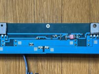
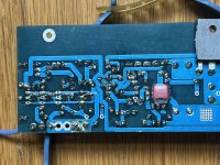
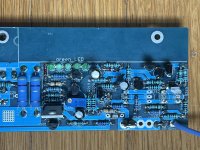
I can't see anything wrong on pictures
now, usual drill - check all resistors - value@position
check all semis with diode test ; if doubtful (including problems testing in circuit) - compare two channels; if still doubtful - pull it from pcb and test (diode test good for BJTs) most likely good for mosfets too, at least if looking for shorts
check for shorts between pads
check orientation of diodes, same as placement ;
were leds lit when you powered On?
Thanks. How is the diode test done?
On the left channel the LEDs all light. after 10-15 seconds T202 is getting hot.
On the right channel, only 4 of the 5 LEDs light as the bulb gets bright.
On the left channel the LEDs all light. after 10-15 seconds T202 is getting hot.
On the right channel, only 4 of the 5 LEDs light as the bulb gets bright.
do not power it again, before getting green light here
google - how to test transistor with diode test
practically, you can test any bjt as two diodes
you'll find it and see
only 4 of 5 leds means - 4 are OK, while 5th is shorted (and allowing current to first 4)
either shorted solder pads, or torched to short with soldering
google - how to test transistor with diode test
practically, you can test any bjt as two diodes
you'll find it and see
only 4 of 5 leds means - 4 are OK, while 5th is shorted (and allowing current to first 4)
either shorted solder pads, or torched to short with soldering
Focusing on the left channel only for now. Checked all resistors, diode orientations, looked for solder bridges between traces. Did diode test on transistors. T204 was suspicious so I pulled it and put it in the component tester: "unknown or damaged part". Pulled T104 from right channel board, tested good, and installed it in left channel. Now the dim bulb test is acting like it did previously with the right channel: bulb goes half right, fades, then goes full brightness. LEDs on board are not lit. Unplugged quickly.
I'm wondering if setting the potentiometers to midway between clicks on at CW and CCW is good enough? If I measure the pot resistance, which pins and what should the value be to start with?
I'm wondering if setting the potentiometers to midway between clicks on at CW and CCW is good enough? If I measure the pot resistance, which pins and what should the value be to start with?
find a reason why LEDs are not lit
either some of them is dead open so entire link is not working, or JFet (LED CCS) is gone dodo, or either T202 or T204 are having shorted base, so drawing current from LEDs
repeat diode test on all transistors and go from there
also check LEDs with diode test, each one - expect something under 2V reading if OK
Last edited:
Progress! After checking everything again I was getting results I wasn't sure of from the diode test of T201. I pulled it out of the board and it passed the first try in the component tester, but then failed repeated tests. So I transplanted a replacement BC546 from the other channel and tried the dim bulb test once more. This time the bulb went on (PS charging caps I assume), dimmed for a second, then went back to full but normal brightness. All 5 LEDs were lit so I left the board powered up for 30 seconds to see if anything starting smoking but nothing was amiss. The only odd things (to me) were: M203 seemed to get hotter than M202 and the bulb was pulsing in brightness. It never went out, just dimmed a little then went back to normal brightness, and so on, at a ~1 Hz rate.
bulb tester is good for testing not loaded PSU
also, to test amp when you know it is biased lightly...... which isn't the case with J2 - it is certainly biased at least to half Iq
so, if you don't have Variac to bring amp slowly while observing Iq and output offset, there is no other way than to have faith in your assembly, put DVM to observe Iq, second to observe DC Offset, to short inputs, then pray and flip power On
in short - no use of Bulb tester when you have serious current for proper operation of circuit
if you have it, bulb tester is resulting in circuit starved with voltage, and no way of having proper operation
Bulb testers and variac is for weaklingssezzzz
LOL…are we fearless greedy boyz?!
Always biting nails on first power up…then say screw it…and little prayer at same time
Always biting nails on first power up…then say screw it…and little prayer at same time
chromenuts, the sentence you wrote, that's the exact way I'm doing.
Remember first power of Gilmore's Stax T2 clone PSU, with various HV lines... I plugged the wall wart all the way from the opposite side of the room. Fearless to a certain extent I suppose

Remember first power of Gilmore's Stax T2 clone PSU, with various HV lines... I plugged the wall wart all the way from the opposite side of the room. Fearless to a certain extent I suppose
heck
I'm not even powering my amps at all ....... I'm sending them to chromenuts for first powering On
I'm not even powering my amps at all ....... I'm sending them to chromenuts for first powering On
I wasn't going to use the dim bulb because my last build went perfectly. Then I saw some reports by @ItsAllInMyHead and that changed my mind. No regrets! 🔥💣🌋💥
@Zen Mod
Don't worry, the bulb was just for the initial smoke test. Will set bias and offset with full PSU current.
@Zen Mod
Don't worry, the bulb was just for the initial smoke test. Will set bias and offset with full PSU current.
Last edited:
Full power test of the left channel (no dim bulb):
- Board Input grounded, nothing attached to output. LEDs lit, no smoke, no smells, heatsink got about as warm as my M2X. Seemed normal.
- One voltmeter across R236 (1R/3W) and another voltmeter across output + ground.
- Adjusting P202 didn't change the voltmeter values much. Turning it I could get the bias on the 1W resistor up to 835mV maximum. Midway on the pot resulted in ~750mV.
- Adjusting P201 affected the output voltage offset a lot. I couldn't get it to settle down: after careful adjustment it would dance +/- 0.5V around zero, then after a few seconds start climbing to +2V. IOW it wasn't stable even after coming up to temp for 20 minutes.
- Disconnected the meters and tried playing music. Had to really turn up the preamp and the sound from the speaker was a bit distorted but still not loud.
- Home
- Amplifiers
- Pass Labs
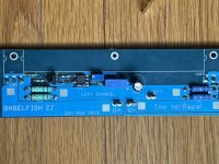
- Babelfish ᄅſ....or FW J2 on Steroids .... or Not your Father's J2!