which 1R resistor?
if you're getting 0V82 at 1R resistor in OS, there are 2 of them in parallel ........ so you already have 1A64 there
regarding waking up - circuit is behaving - both offset and Iq are there , right off the bat
culprit for waking up must be somewhere else - bad contact of probes or whatever
don't hurry - recheck everything again
mistake you had with two transistor pins is critical,things as that did happen to all of us but they're simply not allowed as you gain experience ....... you were lucky of not having half amp gone in flames....... or smoke
Yes. I agree. My lesson was that even if it was ok during assembly, I should double check before power. I realize I was very fortunate there was not more damage.
Yes, 0V82 at output 1R resistor, with 2 in parallel. Could SJEP120R063C2 do more ? Are there limitations in other components? Heatsinks are about 45C. What is your recommendation?
Thanks
I think ZM was using 1A8, so you could safely take it to 900mV. Probably further, but I’ll leave that to him.
1A8 is nice value
little reminder:
regarding DC offset- if you have Iq you wish, but you still have some positive DC offset , while getting to end of rotation of P101, then you must increase resistor in series , which will more open lower output Mosfet
little reminder:
P102 is for Iq set, while P101 is for output DC offset chase
if you need more of any, just increase resistor in series with trimpot
for instance, R123 goes to 510R, R118 goes to 1K2
do not forget to go back with trimpot before powering up
everything referring to schm in post #1
regarding DC offset- if you have Iq you wish, but you still have some positive DC offset , while getting to end of rotation of P101, then you must increase resistor in series , which will more open lower output Mosfet
Last edited:
Some bad news for my build. I had warmed up the amp for about an hour or so this weekend and the sinks were getting to the point that I couldn't touch them for more than a few seconds. A little too warm for my taste. So while attempting to decrease Iq to 650mV per side I believe I shorted V+ and V- on the right channel due to a loose faston connection. A small magical flame and puff of smoke erupted from my SSR speaker protection board then the main chassis fuse blew. I have yet to really assess the damage to the right channel or anything else for that matter. I know for sure the SSR is kaput. Hoping I didn't damage the SS in that channel. That would be a sad, sad day. I also need to see if I did any damage to my right speaker, a Lii Audio Crystal 10. 

You've increased the loop area by separating the ground wire from the V+ and V-. On the same subject you have a large loop in your speaker out and ground wires.
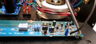
Another thing I noticed was the power transformer orientation. My experience with Antek transformers is that it matters. Rotate the transformer to find the position of least noise. My experience is to have the transformer oriented such that the wires leave the transformer at six and twelve o'clock positions for least noise.
I took some time yesterday to loosen my toroid and run exponential RTA while rotating the trafo. You are absolutely right - the Antek has a ‘sweet spot’ and the measured difference was quite obvious. Thanks again for the tip!
Great experiment Cody. Did you find the relative position was close to Ben’s at six and twelve?
Some good news on my adventure, apparently the SSR did its job and my right Crystal 10 appears to be in good shape. I played them on my ACA with Wayne’s BA2018 linestage for a few songs. They still sound perfect. No rubbing or noticeable distortion from the right speaker. So that’s a relief. Thank you jhofland, XRK971, and JPS64 for a fantastic speaker protection board. I still need to find some time to dive in to evaluating what happened to the amp itself. Fingers crossed!
Some good news on my adventure, apparently the SSR did its job and my right Crystal 10 appears to be in good shape. I played them on my ACA with Wayne’s BA2018 linestage for a few songs. They still sound perfect. No rubbing or noticeable distortion from the right speaker. So that’s a relief. Thank you jhofland, XRK971, and JPS64 for a fantastic speaker protection board. I still need to find some time to dive in to evaluating what happened to the amp itself. Fingers crossed!
More good news and a bit of bad. The bad news is, it looks the short took out the BD139 and BD140 in the right channel CapMx. I’m unable to adjust the voltage on either rail. So the positive rail is at about +24V and the negative rail is stuck at about -27V. So that PSU needs a little work to get back into shape. Now the good news. Great news! Fantastic news really! I hooked up the right channel to the good PSU and all seems well. Such a relief! ZM, your design seems to be pretty robust to be able to handle a short, blow up an SSR board, and keep going like nothing happened. Well done ZM!
Things were good at first. I added 220 Ohms in series with the Iq pot. This let me go to 0.88 amps per 1R output resistor (Previously 0.82 amps). This channel - right - ran for an hour. Temps were fine. This was with the channel and heatsink bolted to chassis, PCBA vertical.
As a reminder, this has 2 transformers with 2 18V secondaries each.
Then I tried adding the left channel, both pots in the middle. Previously good right channel is now horizontal. DBT is not happy. Disconnected channels and tested each PSU with first DBT , then without DBT, an incandescent bulb 60W on V+, V- for 20 min. Both power supplies tested good, separately and together. DBT stays off .
I checked each component and cleaned between each transistor leg. It looks ok. LED, Zener chain tests good. Now, I seem to have both channels behaving the same way - DBT stays on. Without DBT, input voltages start low, settle at about 17V with a channel connected, all LEDs light up. When the right channel was working correctly, this was about 22V. With channels disconnected, these are about 25V.
I tried without DBT to check if that gave me any clues and since the right channel was just working. Other than making PCBA horizontal, I can't think of any changes from working. I also tried vertical orientation of PCBA, no change.
At this point, I'm also writing this down so that I keep track of what I did.
ZM, others, thanks in advance for any suggestions. I'm stepping away for a bit.
Last edited:
you know the drill - pics
logically , changing orientation of pcb is not going to result in funny transistors having their blood flowing to the head , so - if anything happened, it must be some wire connection
try working on one channel at a time, and when you have it operational , fix it inside the case and do not make further unnecessary changes
many ookups were made exactly with relocation of modules, when wire connections are made in subpar quality - been there, done that
and - you know that bulb tester is intended to use it with amp pcbs only when Iq is very small - only then bulb is not limiting voltage, thus not impeding circuit operation
Thanks ZM. Good info.
I understand what you mean about one channel at a time. I tried both only to check if behavior was the same for both. Whatever I did wrong, I did equally on both.
One further note. I disconnected V- and the Voltage droop went away.
Thanks as always for the fast replies and please let me know if you want to see any of the sections in detail.
Attachments
what's exactly a problem here ?
fact that you're having 18Vdc at rails, when both channels connected?
do you have proper DC offset at output of both channels?
what is Iq ( voltage across 2 of 1R in parallel, so 0R5 effectively)?
so in future - either say "xxxmV across 1R group" ( so I know that you think of group and that you didn't divide voltage value to agree with one 1R) or just say calculated value in A
so, DC offset and Iq are ?
take note that changing Iq in bracket of 10% is not bringing any night and day difference in sound
and - I don't like that fast sockets solution; OK < it's handy, but only if you take care that female end is always tight and only if you remove these plasticky sleeves, so you can squeeze and solder wire properly
lately I'm using (everywhere I can) needle end wire connectors, but always in that way - plasticky tossed, squeezed and soldered wire
what's exactly a problem here ?
fact that you're having 18Vdc at rails, when both channels connected?
do you have proper DC offset at output of both channels?
what is Iq ( voltage across 2 of 1R in parallel, so 0R5 effectively)?
so in future - either say "xxxmV across 1R group" ( so I know that you think of group and that you didn't divide voltage value to agree with one 1R) or just say calculated value in A
so, DC offset and Iq are ?
take note that changing Iq in bracket of 10% is not bringing any night and day difference in sound
and - I don't like that fast sockets solution; OK < it's handy, but only if you take care that female end is always tight and only if you remove these plasticky sleeves, so you can squeeze and solder wire properly
lately I'm using (everywhere I can) needle end wire connectors, but always in that way - plasticky tossed, squeezed and soldered wire
I sure appreciate your help and patience ZM.
Iq is 1.7A, initial offset is about 100mV.
Both channels are in the box, with top on, power on for fine setting.
To respond to your questions, these were the problems at the previous step.
Sometimes, Green LEDs will not light up. When I checked voltages, V+ to Ground, and V- to ground was 17V, -17V. In this condition, Iq was changing a lot every few seconds, from a few mA to about .6A (This is the calculated, full Iq)
I understand that 10% Iq will not change sound much. I did not realize that an additional 220 Ohms will only do this.
For left channel, I changed the offset pot series resistor Rx18 from 270 Ohms (and high end of pot) to 680 Ohms (and low end of pot). I did this because initially offset did not go below 0.5V . After the change, I could get to negative offset sometimes. The right channel did not need this change.
Thanks also for sharing your experience about the connectors. I wanted some type of quick disconnect since I was trying to debug and had 2 power supplies and 2 channels. I started out soldering wires to the cap board.
In the end, your comments made me go back and check everything slowly. I reflowed every connection with solder. Behavior seems nominal now and I hope it stays that way.
Again, thanks for the design, PCBs and helping debug.
- Home
- Amplifiers
- Pass Labs
- Babelfish ᄅſ....or FW J2 on Steroids .... or Not your Father's J2!