because you're Official Baby DiyA Leacher ........ and I'm still working on growing another pair of hands .......
🙂
🙂
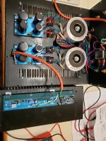
First time power on. Tried only one channel. IRF up, SS down.
What could cause green LEDs to not light up?
PSU seems ok. 50V unloaded. 2x 18v transformers with 2 secondaries each. It drops to 36V when channel is connected. No problem with DBT. SS gets warm, IRF does not.
I didn't notice the green LEDs until Iq with pot max at 100mV or so across one of the 1 ohm resistors.
Should I try other channel in case a bad part somewhere?
Thanks in advance.
pics?
path for green leds is simple
orientation of leds is critical - there is small C at cathode pin
also 1N4148 orientation
path for green leds is simple
orientation of leds is critical - there is small C at cathode pin
also 1N4148 orientation
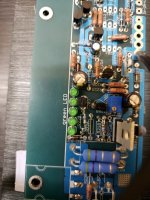
Oops. Here are pics. Not final.
LEDs are oriented correctly I believe, with the C. I checked each one individually with diode tester on multimeter and they each light up. They measure about 1.86V . 1N4148 measures about 0.62V.
LEDs are oriented correctly I believe, with the C. I checked each one individually with diode tester on multimeter and they each light up. They measure about 1.86V . 1N4148 measures about 0.62V.
Attachments
you checked orientation of each LED in situ, on pcb ?
check underside of pcb that you don't have any shorts
test with diode meter D to S of MMBF5486 JFET - it must be several tens of ohms
you can also figure where to temporary solder , from D to S 3K9 resistor, to act instead of JFet , to check is it JFet or something else
check underside of pcb that you don't have any shorts
test with diode meter D to S of MMBF5486 JFET - it must be several tens of ohms
you can also figure where to temporary solder , from D to S 3K9 resistor, to act instead of JFet , to check is it JFet or something else
Thanks ZM. Your responses are much appreciated.
T102 was somehow squished enough that 2 terminals were touching. Though it measured ok, I replaced it. Green LEDs ok now.
Voltages are at +/- 22V for this channel.
Iq pot now runs out at 40 mV across 1ohm resistor. Hope something isn't kaput.
Using SJEP120R063C2 for M103, IRFP150 for M102
T102 was somehow squished enough that 2 terminals were touching. Though it measured ok, I replaced it. Green LEDs ok now.
Voltages are at +/- 22V for this channel.
Iq pot now runs out at 40 mV across 1ohm resistor. Hope something isn't kaput.
Using SJEP120R063C2 for M103, IRFP150 for M102
I'm sleepy now, believe it or not
we will proceed tomorrow
isn't it T202? (not T102)
measure voltages across R209, R213,R217,R218, write here
inputs grounded, no load on output, mosfets bolted to heatsink
we will proceed tomorrow
isn't it T202? (not T102)
measure voltages across R209, R213,R217,R218, write here
inputs grounded, no load on output, mosfets bolted to heatsink
Thanks ZM. Your responses are much appreciated.
T102 was somehow squished enough that 2 terminals were touching. Though it measured ok, I replaced it. Green LEDs ok now.
Voltages are at +/- 22V for this channel.
Iq pot now runs out at 40 mV across 1ohm resistor. Hope something isn't kaput.
Using SJEP120R063C2 for M103, IRFP150 for M102
You might also verify that R123/223 is 220R or more
Ah yes. My printed schematic is for the 1xx channel. But you're right ZM. The picture I posted shows 2xx.
Cody, R123 and R223 are close to 220R, measured in circuit.
Here are the measurements, following setup mentioned
R209 0.605V
R213 0.420V
R217 0.418V
R218 1.342V
Since these seemed reasonable (and the heatsink was now getting hot after walking the dog) I measured at the 1 Ohm resistor again: ~0.82 V
After some twiddling output offset is +/- 10 mV
This seems a whole lot better than before. Did the parts have to wake up? I hope I don't have a funny connection somewhere.
If these are ok, I'm going to let this be and not change resistors to increase Iq.
I'll probably be out tomorrow. Thanks again for the help.
which 1R resistor?
if you're getting 0V82 at 1R resistor in OS, there are 2 of them in parallel ........ so you already have 1A64 there
regarding waking up - circuit is behaving - both offset and Iq are there , right off the bat
culprit for waking up must be somewhere else - bad contact of probes or whatever
don't hurry - recheck everything again
mistake you had with two transistor pins is critical,things as that did happen to all of us but they're simply not allowed as you gain experience ....... you were lucky of not having half amp gone in flames....... or smoke
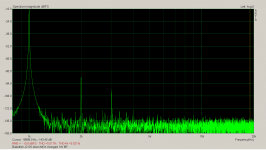
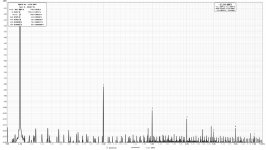
Finally got some noise and other wrinkles ironed out of my measurement setup, so wanted to share this distortion profile. This is my ZMJ2 at 1W/8R with SS in both positions. I messed around with MOX values to coax out some more 2nd – think I ended up at around .32R (.56/.75) on the lower and .40R (.68/1) on the upper.
Attachments


Nice! No doubt I’m adding a good dose of distortion with my MOX values. Since I have my measuring gear in order, I might swap the output MOX back and see how close I get to yours. 🙂
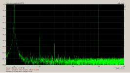
Found it - post 118. And pretty close to my tweaked MOX, so I’m not quite getting the H2 I’d thought from the tweak. Proof, once again, that you were right 🙂 Uploaded both for side by side.
Attachments
later = with changed MOX values , those were tryouts for different OS combinations
what's (of MOX values and positioning) in post #65 is blatant copy of Mithrandir's values, he's having not just better AP1 than I am ( none) but his brain better copes with thinking
🙂
what's (of MOX values and positioning) in post #65 is blatant copy of Mithrandir's values, he's having not just better AP1 than I am ( none) but his brain better copes with thinking
🙂
- Home
- Amplifiers
- Pass Labs
- Babelfish ᄅſ....or FW J2 on Steroids .... or Not your Father's J2!