ZM,
In your three iterations is H2 negative or positive, going with Papa's way of defining it?
How likely is that I will I get a similar spectra to your posted ones. Should I be concerned that my two channels might not have matching spectra? I am planning on using SS at the bottom from the twin pairs I have bought from Patrick/EUVL. If THD spectra a bit different how can each channel be adjusted?
What VCC+/- is recommended?
Are the parts in your complete kit labeled eg resistor to resistor position or are they all together and have to be sorted by the user?
I like the way you have structured and explained this project so that the user can try different iterations and learn from them and make their own personal choice. Thank you.
nash
going with Papaway ...... this Babelfish , I mean all iterations, is having same polarity of 2nd harmonic as original
one will get the same with random output parts (meaning - not especially or at all matched) , considering that NFB is present , diminishing possible differences of xconductance of parts..... so besides setting Iq and offset , no need to headbang about anything else
rails - usual FW format - Donut(s) with separate 18Vac secondaries ; one can go little more (up) with that , but having dissipation of outputs on mind
I'm packing resistors labeled with sharpie on side paper tape , primarily to ease later re-check before final closing of package ; though - trust to no one!
 ....... I had some 1K intruders in group labeled as 100R , sent with Sissy kits ; mixup not made by me , I got them packed all in one 100R bag , but they slipped through my fingers ......
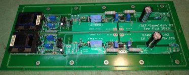
To deluxe 4U
compare , from post #2 🙂
it's made for UMS
(as I'm always whispering : USE 4U/400 !!!!!! )
Last edited:
Probably not so straight on heatsink from modushop. It will need an additional profile I suppose
going with Papaway ...... this Babelfish , I mean all iterations, is having same polarity of 2nd harmonic as original
I'm packing resistors labeled with sharpie on side paper tape , primarily to ease later re-check before final closing of package ; though - trust to no one!
Looking at FW J2 distortion waveform my brain says negative H2.
Labeling the way you say will be great help for us. Nice!
Regards,nash
Probably not so straight on heatsink from modushop. It will need an additional profile I suppose
nope , straight on heatsink , as I see it
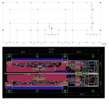
lower half of pcb, mosfets on second row from bottom
arrangement : heatsink , mica , mosfet, pcb , big washer, split washer , bolt
Attachments
Last edited:
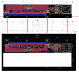
like this ; second (half of) pcb is going in same way on second heatsink
it would be freat thar we have 2 more tapped holes in place where I put green rectangles , so heat sources would be on lower third ........ but it's nice even this way
of course, ZM is ordering directly from Modushop , non-tapped htsnks 🙂
it would be freat thar we have 2 more tapped holes in place where I put green rectangles , so heat sources would be on lower third ........ but it's nice even this way
of course, ZM is ordering directly from Modushop , non-tapped htsnks 🙂
Attachments
Thank's ZenMod all is easy but I'm missing something all the time. How is the mosfet connected to the heat sink since it is mounted on pcb?
post #3 here : Babelfish M25, SissySIT - general building tips and tricks
practically - each pcbs is having 4 holes for heatsink montage ; 2 are occupied with mosfets , other two you're using plastic or metal spacer bushing/distancer , of same height as {mosfet+mica} thicknes
again , written few posts above : arrangement : heatsink , mica , mosfet, pcb , big washer, split washer , bolt
Last edited:
Zen Mod, I'd like your comment on that way of mounting the output FETs.
I believe the shown way is for UMS easyness.
But why would we heat the PCB? The environment inside the amp is hot for sure, but isn't it an additional stress for it (and the other components) to bear this thermal coupling?
I believe the shown way is for UMS easyness.
But why would we heat the PCB? The environment inside the amp is hot for sure, but isn't it an additional stress for it (and the other components) to bear this thermal coupling?
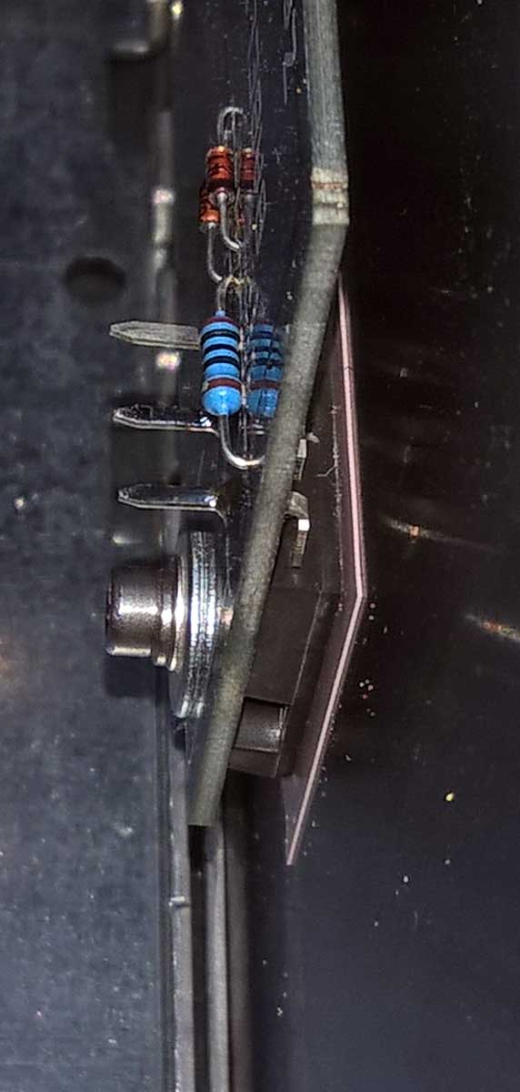
Or you can try the method hereunder with a strip of Nylon or whatever:
vertical "sandwich-mount"
JMP is using it, so you should feel comfortable with it (being french 😀)... not related to this amp though in any way (apart the spacer of course).
@Zen Mod , please remove if unappropriate
Max
vertical "sandwich-mount"
JMP is using it, so you should feel comfortable with it (being french 😀)... not related to this amp though in any way (apart the spacer of course).
@Zen Mod , please remove if unappropriate
Max
another one ...... either Small Glory or Major Flop!
OK, it can be semi flop , considering that M2 variant is not critical in any way , but we'll see how much SEF In Vivo is close to LTSpice one

It had better be major glory, this one I must have

- Home
- Amplifiers
- Pass Labs
- Babelfish ᄅſ....or FW J2 on Steroids .... or Not your Father's J2!