To all that celebrate - Wishing you and yours a very happy Thanksgiving. I'm thankful for having found this lovely community.
For those in other parts of the world or those that do not celebrate - Wishing you a lovely day and many to follow.

For those in other parts of the world or those that do not celebrate - Wishing you a lovely day and many to follow.
I put together a little checklist so it's not really a BOM but better than nothing right? I only did this for SissySIT #2 so builder beware, be sure to double check.
@Dennis this might be handy for you as now you have a good reason to build your SissySIT

@Dennis this might be handy for you as now you have a good reason to build your SissySIT
I replaced the Mosfet on the drifting channel. @170mA the mosfet tested Vgs of 4.1V. The ones in my 2nd kit also measure 4.1. I cut the pins removing it from the PCB, so I have some more Mosfets on order from Digikey. Hope I can get 4V+ Vgs in the batch I ordered. I should learn to have more patience in solder removal, because this time it is costing time and money.
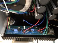
When I went through the drifting channel checking for any other things, it turns out the screw on the SIT with the wire and eye connection was not very tight. I suspect that poor connection may have been problematic. I tightened it up.
The channel was better to bias after these updates. Still a little drift/float, but I decided to call it "good enough" and go into field testing. I lent it to a friend for a few weeks while I finish his 2nd F5 Turbo V3. When that's done I'll build SissySIT #2 for me, I need 4 channels to run in my active horn system.
I listened about an hour at my friend's house yesterday. He's running Alon LotusSE speakers. The sounds was really nice in his setup: beautiful detail, instrument air/separation, great in bass, mids, and highs. He left the amp on all night and reported it is "blissfully sweet" on some classical this morning, and he will be listening all day while he works. He has big bryston monoblocks, F5, and Aleph J monoblocs. And soon to have F5 Turbo V3 monoblocks. It's always interesting to hear his listening notes.
ZM - my Mosfets arrived. I did a quick measurement. 11 of 12 measure Vgs 3.6V - 3.65V at 170mA. One was 3.72V. I tested the high one at 470mA and got Vgs of 3.92V.
I also have a batch of 9240's with Vgs in range of 3.85 @170mA
These 9240's were all tested for matching for F5 Turbo V3 project.
SITs from Pras are 3.4V at 1.8 or 2A.
How big or small is window for Mosfets? Thoughts on using the 9140's or 9240's I have? Is the window OK? Or should I order more to try for different Vgs value?
well, almost no need to worry - I didn't recently saw mosfet , conducting 2A , with 20-24V rail , with less than 4V of Ugs
forget 170mA , that's too wimpy for test
with minimal 300mV for window where Opto is squeezed in , I feel nice
and cozy
and warm
and funny
🙂
forget 170mA , that's too wimpy for test
with minimal 300mV for window where Opto is squeezed in , I feel nice
and cozy
and warm
and funny
🙂
🙂
Thanks! Looks like I'm set to build SissySit #2 when the F5 Turbo is done. There are many projects for the holidays!
Thanks! Looks like I'm set to build SissySit #2 when the F5 Turbo is done. There are many projects for the holidays!

If you look at the schematic, P1 is located between Pin 1 of OK2 and R15/VR1. Put the ohmmeter probes at those two locations and measure. Adjust P1 back and forth to confirm that you are changing the resistance, and adjust P1 until you have zero resistance.
This is very important and explains where the setting should be. after looking at schematic the position and 2k marking by the trim pot had me

I was popping fuses like candy on Halloween.
Please put on page #1
Last edited:
So after setting p1 to 0r I am still having high draw to the point of melting fuses.
I have the Vfet and mosfet isolated, where’s the short?
Or is my R47 to small and wanting to become a light bulb?
I have the Vfet and mosfet isolated, where’s the short?
Or is my R47 to small and wanting to become a light bulb?
Attachments
Last edited:
who said that you can put 0R47 there ?
it was said - 0R1
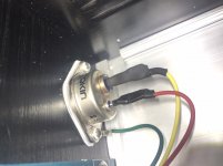
besides that , I can't tell from picture did you made bolting arrangement of SIT properly - can you give us closer photo of same ?
be sure that nothing is in short with heatsink , including mosfet and SIT
it was said - 0R1
besides that , I can't tell from picture did you made bolting arrangement of SIT properly - can you give us closer photo of same ?
be sure that nothing is in short with heatsink , including mosfet and SIT
I have R1 resistors now.
But from what I’ve seen so far it looks like it’s pulling over 10A per channel. 🙁
The power supply is making 24V +/- and working great.
What could pull this much amperage?
Vfet drain to ground measures 100R on left and 1K on right.
Could Vfet bias be starved with R47 and causing runaway?
I can tear it down and build M25...... but first I need advice on testing Fet’s.
Attachments
Last edited:
describe your PSU , +/-14Vdc doesn't make sense , except in case of juicing same 10A on both rails
drain to gnd is not telling me anything - too much things connected , so really not relevant info
buzzer/diode test poor mosfet between all pins ; it's highly possible that you killed poor bugger in first moment
drain to gnd is not telling me anything - too much things connected , so really not relevant info
buzzer/diode test poor mosfet between all pins ; it's highly possible that you killed poor bugger in first moment
Another possible issue - check that there are no shorts to the heatsink caused by long component leads protruding from the bottom of the pcb. The pcb is very close to the heatsink to suit the mosfet thickness so clipping all leads short is critical.
- Home
- Amplifiers
- Pass Labs
- Babelfish M25, SissySIT - general building tips and tricks