Interesting, I just watched a video on testing mosfets. 9240’s are dead so I’ll change them out and pray that the fuse lives with R1 on the negative rail.
be sure to buzz test thinking about PSU caps and their influence
if not sure , just desolder PSU wires
if not sure , just desolder PSU wires
Replaced 9240, 3amp fuse, Checked R15 to #1 =0R, used 3w 0R1 on negative supply, plugged it in and poof blew the fuse and another 9240. It happens so fast I couldn’t even look at DMM’s.
Dim light bulb tester! It won't tell you why it is shorting but at least it will save some components.
@damuffin -
Not to pile on with advice, but:
1) Do you have a dim bulb tester? If so, have you used it to check both the PSU first and then each amp board separately. If not... others may advise, but I'd strongly advocate putting one together and using it to do some quick checks. The behavior seems like a dead short.
2) Did you follow ZMs advice and disconnect the PSU before doing the continuity checks? How do you know you're frying your 9240s? What method are you using to check them?
With due respect, my best advice is to.... Slow down... do one channel at a time. If you actually are frying your FETs why do it in multiples of two at a time?
Hope you get it sorted.
Edited to Add - +1 to Ben Mah ===
I do have a dim bulb tester, but need some guidance on what to test.
The 9240 will have continuity between all pins when it’s fried.
Can I try powering it up without 9240?
I’m going to try cleaning up the gaps around the + - inputs. The traces are very close in this area.
The 9240 will have continuity between all pins when it’s fried.
Can I try powering it up without 9240?
I’m going to try cleaning up the gaps around the + - inputs. The traces are very close in this area.
no power without 9240
though , you can power it without both 9240 and SIT , check your rails to gnd possible short before , then confirm that you have 5V at voltage reg , ref. to GND
pins on voltage reg are in, gnd , out - from left to right , when letters are pointing on ya
though , you can power it without both 9240 and SIT , check your rails to gnd possible short before , then confirm that you have 5V at voltage reg , ref. to GND
pins on voltage reg are in, gnd , out - from left to right , when letters are pointing on ya
Have you ever used your dim bulb tester? i.e. do you know what to look for if your circuit is playing nice or has a short?
Dim Bulb testing is covered all over the place, but a quick and dirty summary (pasted).
1) Hook up PSU ONLY. Test with Dim Bulb. Report back what you see. Stop here if you have a short in the PSU, otherwise move to 2.
2) Hook up ONLY PSU and channel 1. Test with Dim Bulb. Report back what you see.
3) Hook up ONLY PSU and channel 2. Test with Dim Bulb. Report back what you see.
If moving from 2 to 3 is too much of a pain due to de-soldering - then just get to step 2.
When we ask how you're doing something, be specific. Continuity between pins when it's in the circuit or after you've removed it from the board? Don't power it w/o the 9240.
Good idea re: the traces. Per previous advise also - check UNDER the board and ensure no legs are touching your sinks.
Best advice ever... use ZMs above everyone else's. 😀
Last edited:
Unsoldered both fets. 7805 at 5v on right output pin, with light bulb.
If sit is fried would it take out 9240?
Sit drain and source buzz both directions on diode test is that correct?
Thanks for everyone’s help! I hate to post this stuff, but it’s really humbling when your clueless. Haha
PSU is working great, smoking bugs and fuses like it’s fun. 🙂
And my unsoldering skills have never been better.
Last edited:
@damuffin -
I'll let ZM get back to you re: voltage checks. I don't remember anyone telling you to do the voltage checks with the dim bulb tester in place, but it sounds like you've put it in place by saying "with light bulb". Generally, you don't do your voltage checks with the bulb in place... but that's ZM's territory.
Did you do as I suggested and hook up your PSU all by itself with no boards attached and do the dim bulb check? If so, what did you see re: the light bulb? How did it behave?
Don't worry too much about asking follow up questions re: what may or may not get taken out. Answer the questions you've been asked specifically. You have a few yet to answer. I'll pause for now until you get caught up.
It may be easiest to quote the question in your response and then type your response. That way people know precisely what you've done. When you say, "smoking" - are the parts actually releasing the magic smoke, or are you assuming that they're dead? You still haven't answered whether you checked for continuity in the circuit or removed and if you unhooked the power supply per ZMs advice if they're in the circuit.
Not a worry in the world. We've all been there at some point.
@damuffin -
Last silly question (for now) 😀
What are you using between your 9240s and the heatsinks? It's not clear from the pictures. Mica and goop? Keratherm? Ceramic? Just curious.
Really hope you get it sorted out. I'll follow the maestro to coach you through.
Last silly question (for now) 😀
What are you using between your 9240s and the heatsinks? It's not clear from the pictures. Mica and goop? Keratherm? Ceramic? Just curious.
Really hope you get it sorted out. I'll follow the maestro to coach you through.
The PSU is putting out 24-25V on each rail. The light bulb comes on and then goes out once the capacitance is charged. The 7805 is a tiny load so The bulb has no effect.
I’m guessing the sit is broken and taking out 9240 when powered. Any other ideas?
How can I test Sit?
I have the page bookmarked for matching SIT devices can I try that, 24v and 9V on potentiometer.
SissySIT
The devices are isolated and tested with Multi meter resistance.. Keratherm and goop on sit. mika and goop on 9240.
Last edited:
ZM's test will tell you whether your SIT is good for SissySIT voltage and current.
A simple test that gives basic information whether there is a short is this one in post #8:
VFET testing method and result
A simple test that gives basic information whether there is a short is this one in post #8:
VFET testing method and result
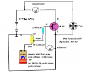
Source,1K,+9v-, grid. (Testing SIT)
Drain to source measures open loop and closed loop without power. I’m unsure if the other measurements are relative to the Tokin.
At the bottom of the test post it says.
“In time, the VFET gate to channel interface breaks down and the VFET will start behaving strangely, leaking and resulting in full breakdown of it's mated BJT, in turn destroying both.”
There are three tests:
1. NO battery. Diode test D-G, and S-G. Should show as diode.
2. NO battery. Connect G to S with 1K resistor in series, measure resistance D-S. Should show low resistance.
3. Battery with 1K resistor in series, positive to S and negative to G. Measure resistance D-S. Should show high resistance.
Best to try this and see what you get.
What do you mean by "closed loop"?
When -9V is applied to G-S, D-S should measure very high resistance as the negative voltage to gate turns the device off.
When you shorted G-S and measured a low resistance, that is expected as the device is turned on fully and D-S is fully conducting.
When -9V is applied to G-S, D-S should measure very high resistance as the negative voltage to gate turns the device off.
When you shorted G-S and measured a low resistance, that is expected as the device is turned on fully and D-S is fully conducting.
I thought it was a positive device so I used +9v.
Closed loop meaning no resistance. Fully connected. OR
Closed loop meaning no resistance. Fully connected. OR
first thing novice need to learn is difference between enhanced and depletion devices , thinking strictly about positive (N) polarity parts , then trying to break own head to grasp same for negative (P) polarity devices
learning how Triode is working is useful , giving basic for later musings
learning how Triode is working is useful , giving basic for later musings
Attachments
This is the 6th papa type class A amp I’ve built, and I’m still dodo that can follow instructions. 🙂
The biggest problem is the 12 months from last build.
D-S measures 0r4 without power, and 0m1 with -9V to grid, 1K, source.
Is there any other tests I can do while Fets are removed?
The biggest problem is the 12 months from last build.
D-S measures 0r4 without power, and 0m1 with -9V to grid, 1K, source.
Is there any other tests I can do while Fets are removed?
- Home
- Amplifiers
- Pass Labs
- Babelfish M25, SissySIT - general building tips and tricks