Volt meter says no conduction. But smoking puff and fried 9240 is suggesting something else. The spec looks unusually shiny like mercury. If vout (pin7) gets 5V what happens?

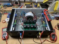
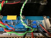
Sissy #2 was finished now is in bias / cooking mode. This one is much more stable than #1 with respect to coming up to bias and holding offset.
Differences are:
I bought all new Bourns trim pots with the legs aligned.
9140s are from an order I made
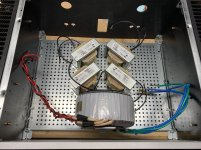
I noticed my snubbers (Rs, Cs, Cx) were after bridge rectifiers, not before.
Tranny is antek an-4218, #1 has AS-4218
#1 has 180k parallel resistor on R19
I think build #2 got more attention to every solder joint and wire twist. It’s a cleaner build.
I cleaned up snubbers on #1, and I’ll check bias on it after #2 is stabilized. Can’t wait to put these into my system. Gotta have both with my active system.
Differences are:
I bought all new Bourns trim pots with the legs aligned.
9140s are from an order I made
I noticed my snubbers (Rs, Cs, Cx) were after bridge rectifiers, not before.
Tranny is antek an-4218, #1 has AS-4218
#1 has 180k parallel resistor on R19
I think build #2 got more attention to every solder joint and wire twist. It’s a cleaner build.
I cleaned up snubbers on #1, and I’ll check bias on it after #2 is stabilized. Can’t wait to put these into my system. Gotta have both with my active system.
Attachments
ZM - need some advice. SissySIT #2 output biased up very nice. Right channel input buffer was easy to set to 20 mA and 0 offset. Left channel input is not playing nice.
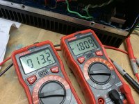
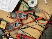
I double checked R6 max and R7 zero. Both are set correctly. I get 13.2 mA and -1.8v initiallly, then I adjust for 20mA, offset voltage climbs up. Adjusting R7 increases offset even more.
Ideas?
I double checked R6 max and R7 zero. Both are set correctly. I get 13.2 mA and -1.8v initiallly, then I adjust for 20mA, offset voltage climbs up. Adjusting R7 increases offset even more.
Ideas?
Attachments

It works much better with 47k in R18. 12 ohm resistor makes 9240 go to heaven.
1amp fuse plunged into power biased up to 128mv on 0R1 resistor and still adjusting.
When I measured 10V offset earlier today with bulb test That was clue.
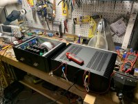
Now wife can have kitchen back tomorrow. 🙂
1amp fuse plunged into power biased up to 128mv on 0R1 resistor and still adjusting.
When I measured 10V offset earlier today with bulb test That was clue.
Now wife can have kitchen back tomorrow. 🙂
Congratulations - i have some minor issues of my own so i can appreciate progress. Just in time for Christmas ;-)
ZM - need some advice. SissySIT #2 output biased up very nice. Right channel input buffer was easy to set to 20 mA and 0 offset. Left channel input is not playing nice.
I double checked R6 max and R7 zero. Both are set correctly. I get 13.2 mA and -1.8v initiallly, then I adjust for 20mA, offset voltage climbs up. Adjusting R7 increases offset even more.
Ideas?
source resistors are 39R and trimpots are 100R ?
be sure that all solder joints are pristine
It works much better with 47k in R18. 12 ohm resistor makes 9240 go to heaven.
1amp fuse plunged into power biased up to 128mv on 0R1 resistor and still adjusting.
When I measured 10V offset earlier today with bulb test That was clue.
Now wife can have kitchen back tomorrow. 🙂
!!!!!!!!!!!!!!!!!!!!!!!! how on earth you even had an idea to put 12Rsomething in R18 position ????????
Rabbit Season! 😀
Exactly who are you answering?
With kindest respect, saying "Open circuit" does no one any good. Do you mean when measuring exactly per guidance on your SIT that your ohmmeter is now showing Over Limit => Open Circuit vs 0.1 milliohms?
I'll leave it to better minds. I truly hope you get it working and wish you best of luck. My kindest recommendation (repeated) is to simply quote the exact suggestion you're trying to replicate and provide an answer below it with the measurement you've taken. Better yet, back it up with a photo. I can't make heads or tails of what you're doing. Perhaps others can.
Time for a beer.
😀
With kindest respect, I believe it's Wabbit Season.
You do have your priorities in proper order, however.
Hunt wabbits first, then beer.

IXFN140N20P
I have IXFN140N20P
New product inventory
A long time ago, my friends in Singapore kept 6 copies of THF-51S.
Can be sold if needed, brand new original
3PCS VGS = 3.9v
1pcs 3.91V
1PCS 3.83v
1pcs 3.81
I have IXFN140N20P
New product inventory
A long time ago, my friends in Singapore kept 6 copies of THF-51S.
Can be sold if needed, brand new original
3PCS VGS = 3.9v
1pcs 3.91V
1PCS 3.83v
1pcs 3.81
@Mazeppa - 

Congrats rhthatcher and damuffin - Looks like you both have everything sorted out. 😀
Congrats rhthatcher and damuffin - Looks like you both have everything sorted out.
😀I think I commented sometime earlier how cool this is.
Unfortunately I have not been following.
Just wondering how you like it compared with your other creatures?
I like this one the best, at least on paper (I haven't built it).
Instead of 240/9140, can the circuit easily control devices like IRFP150 and equivalent P Channel mosfets, say 1.5A to 2A bias.
yup
though , for pucks (Berserk xconductance) , more control and gain in bias circ ........ as Indra pointed and I still didn't had time to pursue - opto with darlington in is probably way too go
though , for pucks (Berserk xconductance) , more control and gain in bias circ ........ as Indra pointed and I still didn't had time to pursue - opto with darlington in is probably way too go
What about just an output stage pcb eg like F4 iteration?
I will definitely want to play with that.
I guess you could just leave out the transformer and solder lead wires across pins etc
I will definitely want to play with that.
I guess you could just leave out the transformer and solder lead wires across pins etc
I know you are perfectly able to give an answer to your own questions here .....

xformer is having own charm , but we know that all Roads leads to Rome
xformer is having own charm , but we know that all Roads leads to Rome
Last question.
Just thought of this.
What is impedance across Ip+ and Ip- ?
I am assuming there is some kind of sense resistor (no idea how this device works though)?
Just thought of this.
What is impedance across Ip+ and Ip- ?
I am assuming there is some kind of sense resistor (no idea how this device works though)?
0.65 mΩ primary conductor resistance for low power loss
and high inrush current withstand capability
- Home
- Amplifiers
- Pass Labs
- Babelfish M25, SissySIT - general building tips and tricks