Dear ZM
Sissy R1 board - is 6 off 1N4148 incorrect (should be 5 per channel)?
No track cutting req on r1 board?
thanks
sch is in post #1 of thread, so you can see which positions of D you need to populate
all being 1N4148
so , for SissySIT ( without R mark, so let's call it R.1) that would be positions:
D3, D4, D5
where you found 6 of them?
and while I'm there, do not forget to rotate ZD1 against silkscreen; as on silkscreen , it is correct for Babelfish M25, while for Sissy it needs to be rotated for 180deg
you can try to rotate it for any other angle, but it will not slip in holes

no cutting exercises on "R.1"
Toooo Hot!! Got my SissySIT (R2 boards) up and running over the past two days, no dramas at all, everything powered up by the book, thanks ZM. Readings are all very steady with the offset drifting a bit up and down (maybe +/- 10mV) over time and heatup.
Unfortunately I am running too hot, 60C on the heatsinks and 80+C on the MOSFET. I used the R in my CRC PS to set the Iq, right at 180mV across three 0R33 in parallel, so should be pretty close to 0R1. Little kill-a-watt meter is showing 2A and ~190W at the wall outlet (117V). Power supply is right at +/-23V loaded.
Anywhere else I can double check Iq without getting an actual 0R1 resistor (don't have in the arsenal at the moment). Guess my options are dial down Iq or get a bigger case?
I think you just answered your own question. The actual bias current is of academic interest if you have already determined the amp is running too hot. Reducing the bias will lower the temperature. It is a linear relationship that is predictable. If you like more current through the SITs, then bigger heat sinks are the way to go.
One thing I do is add extra aluminum L brackets inside a chassis to help spread the heat more effectively. I’ve successfully run amps in smaller chassis that way.
One thing I do is add extra aluminum L brackets inside a chassis to help spread the heat more effectively. I’ve successfully run amps in smaller chassis that way.
no Porn, no Glory
you have 180mV/0R11=1A63
decrease it to 150mV = 1A36
or - best solution - leave it as is ( powered Off while you) make Babysitter, you'll get 10C lower temp
you have 180mV/0R11=1A63
decrease it to 150mV = 1A36
or - best solution - leave it as is ( powered Off while you) make Babysitter, you'll get 10C lower temp
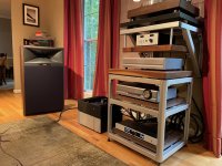
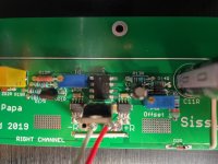
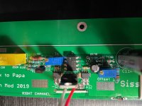
Thanks. Some pics attached, was a little apprehensive to post the pics as I bought a knockoff chassis in a moment of weakness. Was hoping it would be enough since original defisit was in similar. Oh well. Thanks for link to babysitter, knew it was a fan, but did not realize that idea of integral to amp stand. I could not resist at least one hookup to the main system as-is, spooky is right, amazing amp.
Attachments
Last edited:
ok, you sorta properly claimed right to buy knock-off case, already did pony-up for Real McKay, upstream 🙂
shall I say - Fugly! ?
it is spooky amp indeed......... as always - blame Pa
and make Babysitter, pronto
shall I say - Fugly! ?
it is spooky amp indeed......... as always - blame Pa
and make Babysitter, pronto
Hello ZM.
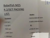
I started to build M25 R.2.
I have some questions.
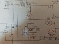
1). There are two 5V6 zener(zd104,105) on schematic but I
dont have 5v6 zener in the kit.
There are two 7v5 zener instead.
2). There are no R121,R122,R126 on schematic
But there are on PCB.
Also no R117,R118 on PCB.
3). Some resistors I didn't use in kit.
390R,750R,18K, I believe that It's depending on SIT or
MOSFET but I don't have any confident.
I started to build M25 R.2.
I have some questions.
1). There are two 5V6 zener(zd104,105) on schematic but I
dont have 5v6 zener in the kit.
There are two 7v5 zener instead.
2). There are no R121,R122,R126 on schematic
But there are on PCB.
Also no R117,R118 on PCB.
3). Some resistors I didn't use in kit.
390R,750R,18K, I believe that It's depending on SIT or
MOSFET but I don't have any confident.
Attachments
Hello ZM.
I started to build M25 R.2.
I have some questions.
1). There are two 5V6 zener(zd104,105) on schematic but I
dont have 5v6 zener in the kit.
There are two 7v5 zener instead.
2). There are no R121,R122,R126 on schematic
But there are on PCB.
Also no R117,R118 on PCB.
3). Some resistors I didn't use in kit.
390R,750R,18K, I believe that It's depending on SIT or
MOSFET but I don't have any confident.
PCB is made for both Babelfish M25 and SET amps, and you got all parts to build amp by choice
1). irrelevant - use 7V5; 8V2 goes in ZDx01 and ZDx02 positions
2). do not populate what is not on schematic
Rx17 and Rx18 are there - already soldered SMD resistors
3). pretty much everything explained in schmtc ( read notes aside); however - I'll try this evening to make some textual and graphic "howto" for Babelfish M25
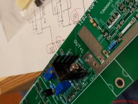
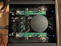
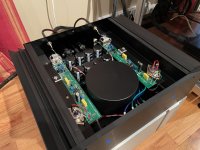
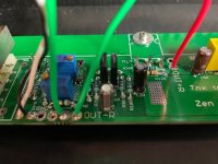
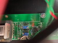
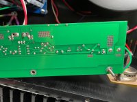
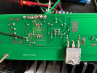
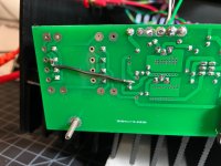
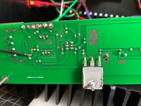
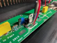
Instead of building a babysitter, I decided to throw Sissy R2 into another case. Now everything was working perfect two weeks ago, just too hot. I had not run it in the smaller case other than the one time in the main system for ~30 mins. All was well on the first channel, but when I hooked up the second channel to power, it started drawing amps way too fast, even with Iq pot turned to 0R. each time I've tried to fire it up Iq starts low (but not 0, more like .3-.4A) and then starts a steady climb to ~2-3A in say 4-5 seconds before I kill the power.
Other than desolder/solder for the power, ground, etc. wires the only thing I had to touch was the MOSFET. I thought I was careful desoldering and did not think I got it too hot, but it is the only thing I can think that could have been damaged.
Any other possibilities on what I've screwed up here?? Thanks!
Attachments
-
 IMG_4471 (Large).jpg267.1 KB · Views: 131
 -
 IMG_4472 (Large).jpg262 KB · Views: 145
 -
 IMG_4473 (Large).jpg313.6 KB · Views: 145
 -
 IMG_4474 (Large).jpg319.9 KB · Views: 138
 -
 IMG_4475 (Large).jpg307.3 KB · Views: 115
 -
 IMG_4476 (Large).jpg250.1 KB · Views: 253
 -
 IMG_4477 (Large).jpg305.5 KB · Views: 259
 -
 IMG_4478 (Large).jpg266.4 KB · Views: 257
 -
 IMG_4479 (Large).jpg272.3 KB · Views: 281
 -
 IMG_4470 (Large).jpg299 KB · Views: 151
Thanks, SIT wiring is the same as it was when it was working and consistent with the working channel, did not disconnect. I thought SIT isolation as well, but that all seems fine, resistances between chassis and all SIT/mosfet pins are the same on both channels. Mosfet is isolated with ceramic, so hard to screw that up (I think...).
diode/buzz check of mosfet?
practically, it is only thing which can go Dodo, SIT being veeery tough beast
if you have any IRF9140/9240 around, replace it
it can be just coincidence (it happens more often that we could expect) - Mosfet being fed up of too much heat in previous case
practically, it is only thing which can go Dodo, SIT being veeery tough beast
if you have any IRF9140/9240 around, replace it
it can be just coincidence (it happens more often that we could expect) - Mosfet being fed up of too much heat in previous case
I have mosfet failure on two occasion due to excessive heat. I fixed with mica sheet and thermal grease for better heat transfer
I have 9240s (both matched pairs/quads and some random), does matching with other channel matter or worry about that if it works?
The quest continues. Swapped the mosfet and no change. I noticed on my quick 2-3 second power ups/downs the LED pilot light (off the positive rail of the PS) goes out immediately, which is weird for any of these amps in my experience. So on one power up I checked and the positive rail only makes it up to ~20V. On the next I checked and the 5V regulator is not outputting 5V, more like tenths of a volt. So something is fishy with the bias circuit, any thoughts on how to diagnose from here? Disconnected the power on the bad channel and the good channel still makes music, so that's good!
- Home
- Amplifiers
- Pass Labs
- Babelfish M25, SissySIT - general building tips and tricks