I purchased a WA68 chassis from an AliExpress merchant for my SissySit.
Hi,
May I ask how smooth is the back of the heatsinks?
Dennis
The back is fairly smooth. There are very fine machining lines across the surface. I have never purchased a DiyAudio case so I have nothing to compare with. I suppose the surface could be sanded at the contact areas if there is concern, but I don't think it will be an issue.
Hi Ben Mah,
Thanks for your comment. It looks like the heatsink is in one piece.
If one is using a bracket then flatness and smoothness will be important.
I think those machine lines can be sanded out as long as the heatsink
is flat.
Thanks,
Dennis
Thanks for your comment. It looks like the heatsink is in one piece.
If one is using a bracket then flatness and smoothness will be important.
I think those machine lines can be sanded out as long as the heatsink
is flat.
Thanks,
Dennis
Yes, the heatsink is in one piece. The base is 10mm thick and the grooved fins are 40mm long. The heatsink back surface is machined quite flat. I don't have a precision straight edge to check flatness but it appears flat when I checked it with a regular straight edge.
I suppose an un-machined hot rolled angle is possibly not perfectly flat either.
I will be mounting the board and transistors directly on the heatsink so it won't be an issue.
I suppose an un-machined hot rolled angle is possibly not perfectly flat either.
I will be mounting the board and transistors directly on the heatsink so it won't be an issue.
Calling ZM
planning to try and get some measurements - is there anything that would be particularly informative ??
My plan
1. Current draw from both pos and neg rails ( so far I have based everything off neg rail draw. Problem ?? without load - rails are equal and under load, positive drops 2V more than negative, I suspect the positive rail is seeing more current draw than the negative )
- I will record unloaded and loaded
2. Will check initial voltage reference from VR1 - should be 2.5 at baseline without current flowing and based on what baggerbole mentioned, should come up to 3.3 at 2A
3. will measure voltage at gates of FET and SIT - per original schematic, SIT should be around -3.5V and FET around -4.2V at 1.6A as measured at pins 4 and 3 of PC817 respectively.
anything else that I can check while I am at it?
Even though the offset settles quickly - I know that the amp is not working as it should and the high current makes me feel a little uneasy hooking it up to my system in case something fails.
..dB
planning to try and get some measurements - is there anything that would be particularly informative ??
My plan
1. Current draw from both pos and neg rails ( so far I have based everything off neg rail draw. Problem ?? without load - rails are equal and under load, positive drops 2V more than negative, I suspect the positive rail is seeing more current draw than the negative )
- I will record unloaded and loaded
2. Will check initial voltage reference from VR1 - should be 2.5 at baseline without current flowing and based on what baggerbole mentioned, should come up to 3.3 at 2A
dBel84:
You can check the ACS723 carefully.
You should read on pin 7 +2.5V at Iq=0A
and +3.3V at Iq=2A (400mV/A).
Caution! The Pins are very near, don´t make a short.
3. will measure voltage at gates of FET and SIT - per original schematic, SIT should be around -3.5V and FET around -4.2V at 1.6A as measured at pins 4 and 3 of PC817 respectively.
anything else that I can check while I am at it?
Even though the offset settles quickly - I know that the amp is not working as it should and the high current makes me feel a little uneasy hooking it up to my system in case something fails.
..dB
if load is not connected , and there doesn't need to be load connected - rails are loaded/burdened equally ......... simply because current going from one rail must end in other rail ........ no other possible path
difference is present , but small and insignificant - positive rail is feeding 7805 , which is feeding ACS chips .....
I'm really puzzled what could go wrong ........ you said that you had D1 and D2 for some time , but you removed them ......
was there anything you didn't speak of ?
difference is present , but small and insignificant - positive rail is feeding 7805 , which is feeding ACS chips .....
I'm really puzzled what could go wrong ........ you said that you had D1 and D2 for some time , but you removed them ......
was there anything you didn't speak of ?
I too am confused.
1. Load - when I say load, I am talking about the amp channel - if it is not connected, there is no load on the psu and the rails sit at around 27V , when I connect the amplifier channel = under load, the rails are not equal, they sit at about +23V and -24.7V ( this is from memory which is why I was going to repeat this experiment )
2. D1 and D2 were only connected for the first time I tried this and could not set current, after this you identified the error and I clipped them out.
The left channel comes up smoother than the right but I cannot adjust the Iq lower - it settles at 2A and offset can be easily set to zero without any modification.
The right channel runs closer to 2.8A and I had to modify R18/R19 to 25K before I could zero the offset. I cannot adjust Iq lower with P1
For both channels = P1 will increase the Iq if I adjust it clockwise but reducing R15 does not decrease the current that the amp settles at naturally.
Nothing else done or changed that I have not mentioned.
psu - fully separated dual CRC supplies , only thing in common is the iec and power switch
..dB
Last edited:
I hope your memory is playing with ya , or something is wrong with PSU .... say that some 100-200mV is OK , counting on usual tolerance in xformer windings (effective impedance) and diode bridges drops ...... but 1V7 is too much
OK < one can live even with that , if reason is unequal windings , not some other reason
regarding behavior of your channels ....... all already assembled amps (be it B. M25 or Sissy) , shown here or not , came to life without any other complication than usual mistakes in assemblage , most of them cured with help of my own copyrighted Futile Attempts Method
I can't be sure , but now is time for thorough testing of traces and vias ; put printed schematic in front of you , put DMM on buzzer and go for it ...... having another DMM on ohms is handy
there must be some reason ....... I said I hate any sort of jacks on pcb from my own (twisted or not) reasons - mostly years in service work and all troubles I had with bad contacts ....... I can't stop thinking that there is some major ookup made with these jacks , even if I can't see anything suspicious or logical
regarding change of R18/R19 ..... I believe I told you to increase them to first higher standard value ..... and that Iq setting is of primary importance , while DC offset setting is secondary thing - easy to get done , once when we understand what's happening
btw. CW or CCW ..... I never remember where these are ending , I'm always looking at multimeter while fiddling with trimpots
I tried what you said first and increased R18/R19 and Offset became more of a problem - I didn't let it do past 2V, no idea where it might have ended. Lowering the resistance sorted the problem and I was able to zero offset
"and that Iq setting is of primary importance" - this is my exact concern, why do I have a default situation of "full steam" and fiddling with the trimpot only increases the amount of steam.
I have a situation where I have current flowing regardless of the control circuit that has been so elegantly designed.
I was trying to understand the exact condition needed for the current to flow- perhaps this is where you could help my understanding and allow a little deconstruction of the events to isolate the problem
I can understand a simple mistake with soldering - the fact that both channels are symmetrical make this even more likely as I built them in parallel. Board damage is much less likely in this scenario ( but not impossible )
I do not want to do irreparable damage which is why I have taken a step back to reassess and use some of that limited grey matter that still clunks in my head.
hopefully my pain can be of help to others - gotta look on the bright side 😀
..dB
believe me , even with handful (just?) of finished amps (also several of them in making , but some of them already put to life on Lab PSU) , I'm sorta half-exhausted with amount of necessary support (most of it off the forum) ....... 
which is in absolute contrast with my own experience , assembling B. M25 and SissySIT in half dozen specimens - everything works as intended , without any specific care about Ugs range etc.
I confessed - I made my number of mistakes but luckily all of them during development of amps, some of mistakes made by others resulted in some parts of text in post #1 of this thread
anyway , I can't think of better strategy for your case than - for few days use just schematic in front of you , non-powered amp , DMM(s) and good magnifying glass
be sure that sense pins of ACS aren't shorted ....... I took great care to arrange these contact pads and to solder them adequately ..... checking several times both orientation and soldering .......... ok - not so much soldering as orientation
tomorrow , with morning coffee and as much is possible fresh two cells , I'll save pictures you posted last , and study them (again) ....
now time for some zzzzz
yes, sleep is important and your support is so appreciated
I must confess, I didn't expect any issue as I knew you had brought several to life - teach me to be too confident
I will do just this with the DMM - coffee, fire and buzzing noise, what could not be more peaceful. 😉
Sense pins of ACS was the first thing I checked 😀 , then ensuring no short of opto
then I shrugged my shoulders.
..dB
I would check one by one the resistances ..... I already mentioned that a resistance in the circuit of the jfet (buffer) I discovered that it had an absurd value (150K instead of 1 ohm) and therefore I did not obtain the measurement of the voltage drop waiting.
Removed the R (R8) and mounted the one with the right value everything is back in place.
PS: that R was joined to the others on the same map and had the same color code as the others
Removed the R (R8) and mounted the one with the right value everything is back in place.
PS: that R was joined to the others on the same map and had the same color code as the others
Last edited:
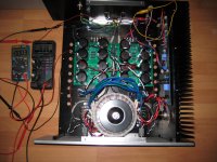
I completed the right channel last night and after much trepidation, I fired her up this morning. Fortunately there were no surprises and all went well. It is cooking at ~1.6A right now with negligible offset. I will probably leave the bias as is for now and set up the front end bias and then check with a speaker. Then onto stuffing the left channel board.
The only issues I had were drilling and tapping the heat sink for M4 screws to secure the IRFP9140 and finding that the hole in the IRFP was too small. I drilled it out with no problems. Also initially I couldn't fit the Cinemag transformer into the board holes. After much fiddling I found that the transformer fitted when offset towards the edge of the board. See ZenMod's post #62 for a clear picture:
Babelfish M25, SissySIT - general building tips and tricks
After about a 45 minutes, Iq has crept up to 1.76A and the heat sink is warm to mildly hot. My cooking thermometer measured 38 degrees C at the outside face of the heat sink base at the IRFP location. Ambient is about 20-21 degrees C.
The power supply is at 22.4VDC positive and negative, with Antek AS 3218 transformer in mono, and AC is 119V.
Attachments
.......
The only issues I had were drilling and tapping the heat sink for M4 screws to secure the IRFP9140 and finding that the hole in the IRFP was too small. I drilled it out with no problems. .........
I've done that before , but now I'm finding stainless steel M3 better solution - no funny heart while drilling mosfet ceramics .....
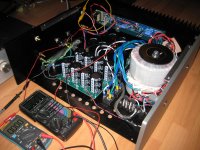
Very nice dual mono setup Ben! Do you hear any EM noise from the Cinemags? Do you think you will need to make a shield?
Another question in general and maybe Mighty Zen Mod may know - is there any sound quality or tone difference between the Edcor or Cinemag? Cinemag - high nickel (80%) or normal (50%)?
Another question in general and maybe Mighty Zen Mod may know - is there any sound quality or tone difference between the Edcor or Cinemag? Cinemag - high nickel (80%) or normal (50%)?
me likee
still semi-fugly!
🙂
Thank you, Zen Mod, and thank you for the fine design and instructions.
I set up the front end and music is coming out of my test speaker. I had a moment when there was no sound, but then I realized that I had forgotten to close the jumper.
Now off to stuffing the other board.
- Home
- Amplifiers
- Pass Labs
- Babelfish M25, SissySIT - general building tips and tricks