It is left channel only. I noticed the bias goes up also if I connect multimeter on output to check offset (without input shorted). When I remove the input short, the bias goes down to 30mv now, so setting the buffer to 20mv is difficult.
The other channel is fine, though.
The other channel is fine, though.
what exactly you replaced after misfortune Blowup ?
and, just in case - did you got this one, maybe you have same problem with your pcbs , post #1820 https://www.diyaudio.com/community/...-building-tips-and-tricks.329316/post-6469676
it is mentioned in Post #1
though, that can't be related with biasing issue
and, just in case - did you got this one, maybe you have same problem with your pcbs , post #1820 https://www.diyaudio.com/community/...-building-tips-and-tricks.329316/post-6469676
it is mentioned in Post #1
though, that can't be related with biasing issue
Last edited:
I replaced the jensen transformers with Edcor, then I made mistake of not shorting r21 with flying resistor in place, which caused the mosfet to break. This I replaced.
So from when working properly to now, I replaced the tranformer to Edcor and the mosfet (IRFP9140).
So from when working properly to now, I replaced the tranformer to Edcor and the mosfet (IRFP9140).
also, this was second and final ookup I made with these pcbs ( R.2)
#1886 https://www.diyaudio.com/community/...-building-tips-and-tricks.329316/post-6516142
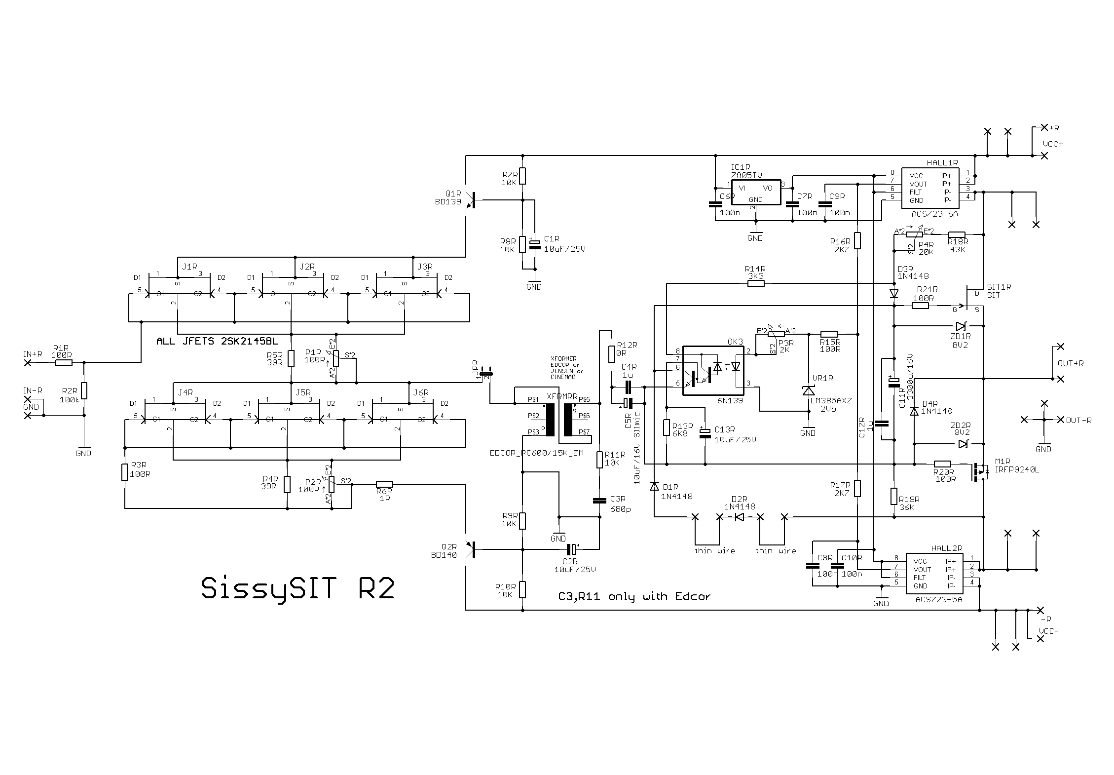
all ref to enclosed schm
#1886 https://www.diyaudio.com/community/...-building-tips-and-tricks.329316/post-6516142
all ref to enclosed schm
Yes, you sent the board with exacto cuts already done, I added a wire as in post 1886 for my jensen transformers. Now with the edcors, can I leave the cut and wire in place?
Thanks, will follow up on the diodes.
Thanks, will follow up on the diodes.
The 1n4148's all show roughly 450mv using diode test DMM.
ZD1R: 380mv
ZD2R: 450mv
ZD1L: 430mv
ZD2L 540mv
This is measured in circuit. Might be wise to replace ZD1 and 2 on both channels, as I destroyed both mosfets, right?

Looking in my stash I have only 9.1v (1.3W) and 6.8v (0.5w) available. Does one of those work?
ZD1R: 380mv
ZD2R: 450mv
ZD1L: 430mv
ZD2L 540mv
This is measured in circuit. Might be wise to replace ZD1 and 2 on both channels, as I destroyed both mosfets, right?
Looking in my stash I have only 9.1v (1.3W) and 6.8v (0.5w) available. Does one of those work?
That was very quick troubleshooting😳, you got it right! The other channel is showing higher bias when I touch the GND of the output as well, so I will replace those Zeners too.
Thank you Zen Mod for your quick guidance!
Thank you Zen Mod for your quick guidance!
I'm not there yet, had to take a break for my better half😉 something still odd though when connecting DMM to output, it still shifts 10mv from 170 to 160mv on negative rails (DMM across 0R1 in line).
Also on left channel my pot is lowest but can't get the buffer Lq lower than 24ma, turning pot only increases it. I believe this was already the case before. Right channel setting 20mv was fine.
I will continue tonight with buffer offset.
Also on left channel my pot is lowest but can't get the buffer Lq lower than 24ma, turning pot only increases it. I believe this was already the case before. Right channel setting 20mv was fine.
I will continue tonight with buffer offset.
no biggie with buffer - is it 20 or 24mA
rare case of needing maybe 47 ohms instead of 39R (R4) , in parallel to 100R trimpot (P2)
but - as I said - no biggie, just set it to minimum and set DC offset
are you having audio GND properly connected to chassis/safety GND, through NTC/whatever thingie?
if there is firm GND, all influences are minimized ...
Yes gnd via thermistor cl60 to chassis, right channel is not showing strange behaviour, just the left channel. Now when touching jumper pin 1 with one probe of DMM lowers the bias again, odd. I will analyse some more tomorrow

you can go at first even without D1 and D2 - they're having role of protection against excessive voltage swing
D3 is necessary part in biasing circuit
D3 is necessary part in biasing circuit
Gents,
I'm reworking my SissySIT, and need your help for a mistake.
I'm troubleshooting transformer buzzing with the winder, and it looks like the toroids are not faulty.
While looking at my grounding, I see 30 ohms between both speaker negs.
I have a double mono PSU, with a star ground for chassis ground. Each cap bank PCBs has a spot for lifting audio ground from chassis ground using a CL60. I suspect the 30 ohms is the addition of the two CL60 in a loop through the chassis ground.
Should I add a wire between both audio grounds and remove one CL60 to break that loop?
If each dual mono power supply has its ground connected to the chassis ground with a CL60, and a CL60 has a cold resistance of about 10 Ohm, then the resistance between the two speaker negatives should be the sum of the two CL60 resistance which would be 20 Ohm. If you measure 30 Ohm you have an extra 10 Ohm.
As a check you can disconnect both CL60 from the chassis ground and measure the cold resistance of the CL60. With the CL60 disconnected from chassis ground, you can measure the resistance between the speaker negative and chassis ground, which should now show infinite resistance.
With dual mono construction, joining of the two audio grounds should not be necessary.
Pictures of your amplifier would be helpful. Include at least one picture showing the overall layout.
I'll do more precise checks, but the two CL60 measure 14 and 15 Ohm in circuit.
And I'll post a picture.
This brainstorming comes from a buzzing behaviour of my toroids, but they don't buzz with no load and the buzz is not changed by a mains DC filter.
I have also tried to replace the four monolithic diode bridges with four MOSFET rectifiers, with the same outcome. That's why I'm questioning my layout, and having a resistance between audio grounds does not sound normal to me... but I'm not educated at all.
- Home
- Amplifiers
- Pass Labs
- Babelfish M25, SissySIT - general building tips and tricks