I used a 10R 0.5Watt metal film resistor for the GBR position..
The amp is dead quiet with no hum or any other noise, not even a turn on thump at start - probably due to the slow ramp up Cap Mx in the PSU.
This is the psu that feeds the dual supply cap mx boards (1 for each channel). Thanks to member birdbox.

The amp is dead quiet with no hum or any other noise, not even a turn on thump at start - probably due to the slow ramp up Cap Mx in the PSU.
This is the psu that feeds the dual supply cap mx boards (1 for each channel). Thanks to member birdbox.
Last edited:

I saw an F8 thread that I thought was different from this one; but cannot find it, so my posting here will only add to the confusion of Babelland, anyway here is my perfusion of ideas.
Right now I have a choked 2SK182, common source. Choke is BIG and weights almost 2Kg. Great sound, see my avatar for the distortion spectrum . .
I am thinking of adding a Schade feedback to that. [Like always. Just for fun. Just as a PASS-time.]
To get there I first show the circuit I saw, added here (somewhere). This is F8 MU-follower with Schade feedback with a SIT or power jFET (SJEP...). The feedback is the trick. So how to configure that?
.jpg")
First, the Mu version, left, of this F8 reference: and then right, Fb added : 2nd H is -70dB with (6Vpp).

Left Spiced reference mu driver. The CCS needs to be big (not a resistor) as the SIT needs current capability; so I took here 20mA. [10 might not be aneamic yet.] Current right should be increased somewhat.
-
My goal is to see how such Fb would work on a choked amplifier. "Naturally I look for any opportunity to improve the performance of a circuit, and because I don’t mind throwing away a little gain, I considered using "that harmfull" (Schade in Dutch means harm. Hmmm. Too bad...) negative feedback on the circuit." And that will not be an F8, just a Shady Ben.
Right now I have a choked 2SK182, common source. Choke is BIG and weights almost 2Kg. Great sound, see my avatar for the distortion spectrum . .
I am thinking of adding a Schade feedback to that. [Like always. Just for fun. Just as a PASS-time.]
To get there I first show the circuit I saw, added here (somewhere). This is F8 MU-follower with Schade feedback with a SIT or power jFET (SJEP...). The feedback is the trick. So how to configure that?
First, the Mu version, left, of this F8 reference: and then right, Fb added : 2nd H is -70dB with (6Vpp).
Left Spiced reference mu driver. The CCS needs to be big (not a resistor) as the SIT needs current capability; so I took here 20mA. [10 might not be aneamic yet.] Current right should be increased somewhat.
-
My goal is to see how such Fb would work on a choked amplifier. "Naturally I look for any opportunity to improve the performance of a circuit, and because I don’t mind throwing away a little gain, I considered using "that harmfull" (Schade in Dutch means harm.
Hmmm. Too bad...) negative feedback on the circuit." And that will not be an F8, just a Shady Ben. Attachments
Last edited:
I just made the GBR in one channel = 0R and that cured the hum. No hiss either from the tweeter with ear 2 cm from dome.
It was really an extremely dramatic change so now one amp is playing music. Iq is just below 1.9A (1.125 V over R17/R19). Rails are -+24.3VDC. I use a power plant so mains AC is regulated to 230.8 VAC.
I don't hear any power-on / power-off sound. My speakers are 94 dB in sensitivity.
It was really an extremely dramatic change so now one amp is playing music. Iq is just below 1.9A (1.125 V over R17/R19). Rails are -+24.3VDC. I use a power plant so mains AC is regulated to 230.8 VAC.
I don't hear any power-on / power-off sound. My speakers are 94 dB in sensitivity.
Yes, both are singing now 🙂
Very detailed and transparent sound and great bass.
Probably best amps so far. I need to listen more.
The signal path is very short. Direct som DAC in preamp mode to F8. Signal only passes one jfet and one SIT on its way to the speakers.
I changed from power plant to take mains after the mains DC-filter. When 2nd F8 was power up the small 300W power plant complained a bit that it was hard loaded. I think it could handle it but will see how it works as it is now.
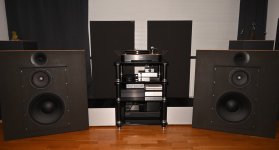
The F8's are the two big boxes at the floor beside the speakers.
After removing the GBR I made the solution below so I only needed to suck up one hole.
That is often the worst part if space is limited to suck up the solder after removing a component so holes are ready to accept a new component.
Very detailed and transparent sound and great bass.
Probably best amps so far. I need to listen more.
The signal path is very short. Direct som DAC in preamp mode to F8. Signal only passes one jfet and one SIT on its way to the speakers.
I changed from power plant to take mains after the mains DC-filter. When 2nd F8 was power up the small 300W power plant complained a bit that it was hard loaded. I think it could handle it but will see how it works as it is now.
The F8's are the two big boxes at the floor beside the speakers.
After removing the GBR I made the solution below so I only needed to suck up one hole.
That is often the worst part if space is limited to suck up the solder after removing a component so holes are ready to accept a new component.
Attachments


I am thinking of adding a Schade feedback to that.
now, there's a trick; Herr Schade never had intention as we are having now - using his name and tricks to mimic triode with non-triode-like part ........ his tricks were made for bettering entire circuit, in most cases much better than simply changing parts in no-nfb circuit and hoping for best; I mean, guy was a Scholar and Engineer, for start

as a matter of fact, any sort of feedback is in general changing transfer function of entire circuit in a way that it can easily resembles having triode in circ, even if there is not one
so ............ call it as you like, but I confess that my predetermined and twisted mind first acted thinking - wtf is now with making triode more triode ...... using Schade feedback on SIT part
anyhow, if you like it, go for it!
sound out of my test bed Yamaha NS-10M
and, non test bed spks?
No Porn, No Glory!
After 2-3 hours I checked the DC offset at speaker terminals. 4 mv for left and 9 mv for right. So no need to readjust.
Amps have played music now for 5-6 hours or so. A good thing is that classical music sounds very good. No fatigue.
I read an article written by Nelson Pass about Intermodulation Distorsion (IMD). I was surprised that an amp with low THD can show quite an amount (several Volts if I remember right) of IMD and that can be the reason for "bad" sound for complex music as Classical music often are. Therefor IMD probably low on this one?
Why we never see IMD spectrums like we see THD?
who cares
I'm dumb, but I have ears
anyhow, after hearing some amps, some being reason and some being result of fame IMD War in 70's and 80's, I decided I don't care.
I could take some of these amps only as gift, just to pull the guts and make something different in same case
if enough sinking, proper amp, if not - proper preamp
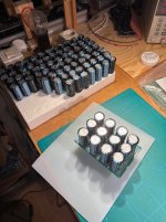
I slammed in 6x6800 per rail for a test rig. Maybe a tad to stressful for the average 150 VA tranny no?
Btw what is papa using NTCs for in the shop PSU boards. As R in C-R-C ?
Btw what is papa using NTCs for in the shop PSU boards. As R in C-R-C ?
For my F8 where i reuse PSU for the M2X I use CRCLC configuration. The CRC is 2 x 33mF for each C and the last C is 33 mF (for each rail).
This gives me very low ripple for 1.4 - 2 A Iq.
I don't think you can say more is better as the high peak currents through rectifier creates noise and transformer should be able to handle it also.
It also depends on Cap ESR how "wild" it gets and which configuration you go for. CRC og just C 🙂
This gives me very low ripple for 1.4 - 2 A Iq.
I don't think you can say more is better as the high peak currents through rectifier creates noise and transformer should be able to handle it also.
It also depends on Cap ESR how "wild" it gets and which configuration you go for. CRC og just C 🙂
Yea, I don’t know the ESR for those Jamicon 35 v 6800 uF, and I can’t measure them either with any instrument of mine. But I have s**tloads of them so I thought I could make some modules for testing trannys and PSU configs.
Probably those Jamicon is not very low ESR but "just" fine general purpose caps. There are mixed feelings about them. I have no bad things to say about them. I have some smaller ones I use now and then for PSU filtering. They also measure fine using a prof LCR tester. According to their own web they are very good 🙂
It is a Chinese brand? but many "quality brand" caps are produced in China anyway.......maybe rebranded Jamicons? 🙂
It is a Chinese brand? but many "quality brand" caps are produced in China anyway.......maybe rebranded Jamicons? 🙂
A mint pair of Rosewood Yamaha NS1000 at the moment.and, non test bed spks?
- Home
- Amplifiers
- Pass Labs
- Babelfish F8