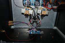
Yes, yes I may have hurried a bit also because my dinner table looks like an electro lab and I wanted it cleaned up a bit and have the 2nd mono block tested and assembled.
I also like this one 🙂

I was not only thinking about myself....... 🙂
I also like this one 🙂
I was not only thinking about myself....... 🙂
gain is not much of an issue, in context of IdssOk, if not matched but Idss still around 6-7 mA will it affect the gain so I will have different gain in the two amps?
At least I think all my SJ74 are matched so I will remember which amp board got the new jfet so I can change the other channel also either "now" or in the future.
Yes......very painful.......but at least I expect to learn something from it 🙂
first, enough OLG and NFB to cover that, and what I did to keep OLG sorta constant, read first posts
I will check what I have. The Idss of the two SJ74 I got......can't remember if it was written somewhere. Will check.....do you have a clue? 🙂

don't stress about Idss, use whatever you have to repair channel
anyhow, for peace of mind, take care to have matched pair, later
anyhow, for peace of mind, take care to have matched pair, later

suspiciossssssss what can be measured in simple way
it seems as partially damaged, so only thorough check/test could show
it seems as partially damaged, so only thorough check/test could show
I took out the SJ74 and the Peak tester recognizes it as a P-JFET with Idss = 8.16 mA. So maybe it works.
I wonder if I should also take out the BC556?
I have BC556A and BC556B. It B the best to use?
Now I know Idss is 8.16 I may be able to find one that is close. The one I found has Idss 6.55 mA (a quad for the J2 which I don't build).
Something must has broken as the offset stayed at 0.2 - 0.3V after it was adjusted to about 10 mV when everything was working.
Now jfet is out I may be able to make better test of the BC556 in-circuit. It is easier to take it out now the jfet is out.
Now with SJ74 out of the circuit I was able to measure the BC556 using the Peak DCA75. It could recognize it as a PNP BJT with hfe = 9 which is a bit low but as it is in-circuit the tester can be "fooled". What I did further was testing using DMM in diode-mode. EB is fine but EC measures like a diode. 0.6V one way with probes and infinite the other way. It seems wrong? .....a fresh BC556 measure infinite both ways. I think I will take BC556 out.
I found a SJ74 that says Idss 9.7 mA. Think I will use that. It is from a quad of 2 x 74 and 2 x 170. Then I have a spare for the other channel and a pair of 170 for another project.
I found a SJ74 that says Idss 9.7 mA. Think I will use that. It is from a quad of 2 x 74 and 2 x 170. Then I have a spare for the other channel and a pair of 170 for another project.
suspiciossssssss what can be measured in simple way
it seems as partially damaged, so only thorough check/test could show
hardly that BC got any stress, but replace it anyway, even if it costs 100E/piece

irrelevant suffix, it's just silly cascode
After replacement of the two transistors amp behaves as before. Not much adjustment needed to be back to former values (offset, Iq).
So now the fine-adjustment when hot and then the functional test without shorting output to input (hopefully).
The BC556 measured fine when I got it out using the peak tester......but so did the SJ74.
So now the fine-adjustment when hot and then the functional test without shorting output to input (hopefully).
The BC556 measured fine when I got it out using the peak tester......but so did the SJ74.
I tested the two F8 amps in my system after fine adjustment of offset / Iq but no music yet. No smoke either so far but a lot of hum. With input shorted total silence. Could it be the 15R GBR that causes this in my system setup?
It is the same system as with Lazy Singing Bush which were very silent.
Think I will try tomorrow and take out the GBR in one channel (and make a short instead) and check if this helps?
In all other amps I have built the input signal Gnd has always been the PSU Gnd. M2X were in the boxes before and those were silent as well.
Could be interesting to hear other F8 builders if they have installed GBR resistor or not.
GBR are there to help/prevent possible GND loop in case of using common PSU for both channels
if building dual mono, GBR can be either 0R or 15R (as per schm), without any functional or sound difference
now, post pics how you did it
my F8 are dead silent even on crummy T-Bed
and I believe I'm not only one who already built it without problems
if building dual mono, GBR can be either 0R or 15R (as per schm), without any functional or sound difference
now, post pics how you did it
my F8 are dead silent even on crummy T-Bed
and I believe I'm not only one who already built it without problems
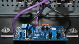
PSU Gnd is at the two black capacitors. PSU Gnd goes to chassis via a NTC (not in picture).
Same PSU as used for M2X which where silent.
Speaker return goes to cap and from there a short wire to PSU Gnd at PCB.
The RCA cables I use for signal is a type with a twisted pair and then a metalized polyester screen that is connected in one end only (at source end).
It is not a traditional coax.
Same PSU as used for M2X which where silent.
Speaker return goes to cap and from there a short wire to PSU Gnd at PCB.
The RCA cables I use for signal is a type with a twisted pair and then a metalized polyester screen that is connected in one end only (at source end).
It is not a traditional coax.
M2X is passive gain/no NFB thingie
even if B. F8 isn't massive gain gadget, it's still more criticall than M2
anyhow, sole thing I can see is - you took GND from PSU to channel pcb from dirtiest place - cap pin
if not done in some other way, where GND takeout is actually taken from point physically away of pulsing currents paths, at least take that wire from cap pin to exact middle of solid core bridge, connecting two caps
there is hopefully "silent" point, where current pumping to left and right cap are nulling each other
and take speaker neg from channel pcb, not from PSU
I have a set of A7 in my basement. No converter however.and second?
though, nothing wrong having just one, if you have proper stereo to mono converter (hint - Iron repeater) and Altec A7

The PSU is a CRCLC so the two caps are after the DC chokes. So should be silent point there.
The CRC is the DIY store PSU boards which is not in picture. Ripple is very low. A few mV.
The hum was massive so moving the speaker return wire from caps to PCB should not make a massive difference?
Also with no input amp is silent so it is not self generated hum from PSU itself.
As the GBR is not needed this could be the first try?
I am here to learn so curious to see what difference it makes to short the GBR.
It is first time I see such a configuration. Normally the ground breakers are between signal Gnd and chassis (at least the ones I have seen in this forum).
But here it is between the PSU Gnd to a new "virtual" signal Gnd.
I will report back tomorrow if there is any difference. If not I will look at the other options.
You should still install the "ground lift" thermistor (or alternate versions). The Hum Breaking Resistor is an option that is normally effective if there is a cross channel hum problem in stereo amplifiers that share a power supply between channels. And it is in addition to the "ground lift", not in place of.
- Home
- Amplifiers
- Pass Labs
- Babelfish F8