My Nutube stopped working last year after two months of occasional use. It wasn't turned on continuously; after turning it on, a loud beeping noise suddenly came from the left channel.

Hi guys!
I bought a Korg Nutube kit that I finally have put together also. It was good fun and easy. I have done several other "pass kits" in the past and usually all is good.
However - I have problems with my Korg. It gives the 9.5 V where it should, but no sound comes out of it except a lot of humming- I have gone through the plans again and again but can not find any error.
As a final resort – should the trimmer potentiometers be adjusted to something specific ? I cant seem to find any information hereon. A certain voltage somewhere that I have wrong??
Any help would be much apprechiated. Thanks, carsten
Hello everyone,
I've built a B1 which is working well so far.
I was wondering if it is necessary to change the bias, which is 9.5V as recommended. I have seen here and there that choosing a voltage slightly higher than 12V gives better results. What's your opinion on this? Is there a real improvement in sound (less distortion)? is there a risk to the Nutube?
Thanks in advance for your enlightened opinion!
Configuration: DSD files, Audirvana Studio, B1 Nutube with linear power supply, AAdac Audio Analogue, PASS F6 diy, Highland audio ORAN + Mosscade TItan Sub. Dirac Live Room Correction.
The trim pots are set correctly if you are measuring at the points given in the manual. Since it seems that this happening to both channels, the power supply is where I would start, checking every single voltage. I had a similar problem and in my case, I had accidently misread the 475 ohm resistors as 475K. Yah, I had no sound either until that was changed. You can bet that it is simple and right in your face. That's good.Hi guys!
I bought a Korg Nutube kit that I finally have put together also. It was good fun and easy. I have done several other "pass kits" in the past and usually all is good.
However - I have problems with my Korg. It gives the 9.5 V where it should, but no sound comes out of it except a lot of humming- I have gone through the plans again and again but can not find any error.
As a final resort – should the trimmer potentiometers be adjusted to something specific ? I cant seem to find any information hereon. A certain voltage somewhere that I have wrong??
Any help would be much apprechiated. Thanks, carsten
Changing the bias voltage gives a different sound character to the unit. In the description, Nelson gives very good advice about choosing what you like to hear. 12 volts won't be a problem, and if you don't like the sound try other settings. Seems like 9.5 volts gives the least amount of 2nd harmonics.
From Nelson's DIY Nutube Preamp writeup (pdf download @ post #1):
After a few minutes and no smoke, we adjust the T7 and T8 voltages as follows:
Voltage at 12 VDC is approximately the 2nd harmonic null point where we get about .3 %
distortion in 3rd harmonics. As we go lower we start getting positive phase 2nd harmonic, and it
will hit 1.5% at 1 volt AC output with about 9.5 VDC on the T7 or T8 test points. Voltages
higher will give negative phase second harmonic.
This is a reasonable calibration - 0.1V either way changes the distortion by about 0.1%
Clockwise on the pot from the null spot makes for less Plate voltage, and positive phase
second harmonic, counterclockwise makes for more negative phase second harmonic.
If you have a distortion analyzer which gives you the percentage but not the phase, then just
start out with the Plate voltage high (CCW pot) and turn it clockwise to the point where it is
minimum, and then go further for + phase, or back up for - phase.
The reference setting for this project, are 9.5V on T7 and T8, which gives a positive phase at
about 1.5% at 1 volt output. You are free to set it elsewhere.
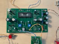
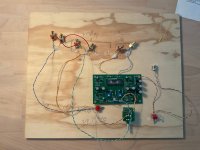
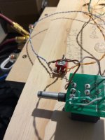
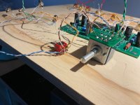
pics? sure, pictures attached in the below. I usually assemble on a wooden board first and the transfer to housing. I have (re)-checked that all components are mounted where they should and simply can not find the error. The problem remains: no sound from either channel except humming. humming can be adjusted with the potentiometer. Any advice is GREATLY apprechiated!
Attachments
Perhaps you have a problem with the wiring of the input RCAs to the input selector to the volume pot.
Double check that wiring.
Post detailed pictures of the RCA wiring, the input selector switch wiring, and the volume pot wiring. Show closeup shots of all of the solder connections, with all wiring connections visible.
Double check that wiring.
Post detailed pictures of the RCA wiring, the input selector switch wiring, and the volume pot wiring. Show closeup shots of all of the solder connections, with all wiring connections visible.
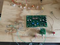
I think that I see potential problem with the input RCA jacks. With each jack, I am noticing that the ground tab connector is between the plastic washers. If, just by chance the washers have a shoulder to them, then this means that those tabs are NOT in contact with the ground, and that tab should be under the mounting nut just to be sure of this important contact. Sure would explain the hum.
THANK YOU-- I checked the wireing and all seemed good- as suggested by Ixnay the hum problem was the washers - I did not know that that could have eben the problem andreplaced them "just to see" - now the hum is gone and it plays....... from one channel (music comes out from one speaker)....ha ha, oh man..... however when I disconnect the output cable from the RCA that works, sound appears from the other speaker....ay..... I assume this means (?) that some of the wireing must be wrong. I looked at the PCB for the potentiometer and did not see a clear connection from the "Ain" pin and moved the cable to the potentiometer instead-- did not help...im not smart enough to figure out how this works.....but its good fun! can anyone figure out what could be wrong based on this?
Attachments
You are welcome. I make mistakes like this very often. Let's go back to the RCA input jacks again. On one of them, I see what appears to be an input wire unintentionally touching the ground. It may be something else, dunno. If there is no problem there, then we can move on to the selector switch.
Last edited:
Looking at the second photo again, I see the brown wire going to the wrong connection. Move it from where it is now to "A in" on the same circuit board. Yes, the same that you had it originally was correct. You cannot see all of the traces on this board. Fools me too every once in a awhile.
Last edited:
Thanks again! I have moved the brown wire back. The ground wires do not touch the input wire on the RCA. Regarding the input selector I have tested with mulitimeter that there is connection in the two positions, i.e. the swich works and the "left" wires are all soldered on one side and all the "right" wires on the other side - should be ok I think? (but I realize that somewhere something is not connected right....)
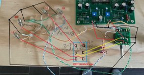
You're doing fine. I would like to see a different view of the selector switch so that I can verify from the switch posts, what wire goes where. Make the view just large enough so that I can tell what color wire goes to each post of the switch. Right now with the photo that you have provided one cannot tell this.
Until you catch up, I have one last observation. As a sort of test, you should swap the green and white wires that you now have tied to ground on the pins sticking out on the board of the RK27 pot. You could also see if combining both of these 'common posts' on the pot will solve your fiasco.
What it seems that you have at the moment, are separate grounds from each input to the RK27 circuit board. That is alright unless the grounds got mixed up. Catch up with the last post that I made first and then continue to this post.
What it seems that you have at the moment, are separate grounds from each input to the RK27 circuit board. That is alright unless the grounds got mixed up. Catch up with the last post that I made first and then continue to this post.
I checked the wireing
principle how it needs to be
remove all wiring, do it again by this sketch
take care of fast soldering pins of switch - necessary because plastic is fragile and easy to melt
if you have helper solder flux ( usually used for smd etc.) or calophone, use that to ease/make soldering faster
Attachments
In other words, get rid of RK27 circuit board, tie all grounds together, and run separate leads for inputs/outputs. Color coding helps you along as well. For example, make all ground leads black, all right signal leads red, and all left signal leads blue.
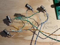
these pictures are from before i put the brown wire back to the "A in" on the potentiometer board. i included a close up of the RCAs also. I sometimes use hotglue to keep the wires from moving around.You're doing fine. I would like to see a different view of the selector switch so that I can verify from the switch posts, what wire goes where. Make the view just large enough so that I can tell what color wire goes to each post of the switch. Right now with the photo that you have provided one cannot tell this.
Attachments
- Home
- Amplifiers
- Pass Labs
- B1 with Korg Triode