WOW! this is sooo helpfull!! makes sense with the coloring scheme!! Great advice 🙂principle how it needs to be
remove all wiring, do it again by this sketch
take care of fast soldering pins of switch - necessary because plastic is fragile and easy to melt
if you have helper solder flux ( usually used for smd etc.) or calophone, use that to ease/make soldering faster
yes I think this is a good suggestion. I will head to the store and get some new wires.In other words, get rid of RK27 circuit board, tie all grounds together, and run separate leads for inputs/outputs. Color coding helps you along as well. For example, make all ground leads black, all right signal leads red, and all left signal leads blue.
Good photos, thanks. What looked to be a wire out of place was just a string of hot glue on one of the RCA jacks.
I will let you get this all rewired and then we will see what happens.
Something that helped me with the larger holes in the Pass boards was to make a U shape or J shape out of the end of the wire. I could then insert the wire shape into the circuit board hole and it would stay put better. You also make a better mechanical contact this way instead of depending on the solder to make your connection for you.
I have actually used the same method but a much smaller J shape for the RCA jack pins. It doesn't work with all RCA jacks though, because some have a different shape for the center pin than others. The Manley brand RCA jacks that I use have a deep cup that will actually hold the 'J' in place really well, and then I solder it.
@Nelson Pass Both tubes I bought were right off the DIY store website. I'm assuming you guys order directly from Korg?
The Nutubes I have were gifted to me. Also, I am not involved in the store purchase.@Nelson Pass Both tubes I bought were right off the DIY store website. I'm assuming you guys order directly from Korg?
Is there anything in the design that could favor L side blowing or a specific component to look closely at? On mine the L channel was cutting in/out so I pulled all the electrolytics on that side and double checked the caps. Replaced with new tube, all good, now the new nutube (haha) has started cutting in out a few times on that same L channel. scratched my head, put it on the shelf and plugged in the iron pre . . . happy days
yes I think this is a good suggestion. I will head to the store and get some new wires.
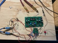
turned out I hade some wires in the drawer. I realize that its not super pretty, but im happy with all connections. the problem however persists. i.e. no suond one the right speaker when both output cables are connected but the right speaker plays well when I disconnect the L output cable...????:
Attachments
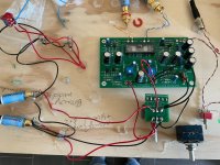
I can't help myself. LOOK at the out RCA jacks/connections. Remember what you had to do with input connections and washers? Do it ALSO to the output.
short update - i re-did the output RCAs and am sure that the ground wires have a good connection to the RCA. This did not help. I have re-checked the rear of the PCB for unintended shortcuts, but to me it looks good.
Since the right output channel works if the left channel is not connected I assume that as such the amp works as it should but there must be so sort of shortcut somewhere. I wonder if this could be within the selector switch if I have applied to much heat to it during soldering?? other suggestions??
Since the right output channel works if the left channel is not connected I assume that as such the amp works as it should but there must be so sort of shortcut somewhere. I wonder if this could be within the selector switch if I have applied to much heat to it during soldering?? other suggestions??
I would omit selector for now. Connect wires for just one channel input rca pair.

small update- removing the seletor switch did not change anything. should I try and take out the volume potentiometer next perhaps?
No, unless your amp has a volume control of some kind or your signal input into the B1K can be controlled. If you can control the input signal before the B1K you can remove the pot and test each channel with each input side (L&R).small update- removing the seletor switch did not change anything. should I try and take out the volume potentiometer next perhaps?
I don't see anything wrong with the pot hookup.

- Home
- Amplifiers
- Pass Labs
- B1 with Korg Triode