SOLD
B1K complete kit, Silver faceplate, PCB already stuffed with resistors. (The gorgeous red PR9372 from Precision Resistive Products) The silver front faceplate isn't quite perfect, but it will still make great preamp for somebody.
This is being sold as fundraiser for Burning Amp Festival. (Thank you to Pete Millett for sending the NuTube!!) All proceeds will go to Burning Amp Fest.
SOLD $245USD + shipping. SOLD Thank you!
Last edited:

New Nutube received, installed and working!
look at the pretty glow.... listening now on my office speakers now and it sounds great. Can't wait to hear it on my main system.
One more question, my measurements all look good except T3 which is sitting at 22.0. Thats more than .5v of the 23v needed. Is that okay or how would I go about correcting that measurement?
22V is acceptable. The 23V is only an approximate number. Perhaps your power supply is not supplying 24V.
Just enjoy your new preamp. 🙂
Just enjoy your new preamp. 🙂
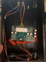
I have some problem when building the B1K pre amp. I am trying to use just 1 set of RCA input and output to simplfy the wiring at this moment. When this preamp is connected. It buzz very loudly and continiously. I think that is because of some silly mistake exist.
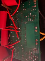
Also, music are only coming out from right channel, where the left channel remaing no sound. I originally tried to use the 0.33uf, 1uf abd 3.3uf (ppp) cap. Then I thought 3.3uf may be too low for my power amp and causing the buzz. So i change it back to 10of bp cap shown in the pic below. The power supply is 24v smps from diystore. I did try to browse throght this thread and doing debug by myself. But i really have no clue now.
T1 to ground +23.9v
T2 to ground +23.15v
T3 to ground +22.39v
T4 to ground +8.89v
T5 to ground no reading 🙁
T6 to ground no reading 🙁
T7 to ground +9.5v
T8 to ground +9.5v
I did double check that there's no cold solder joint and the compoents are at the right position(I think)
Any suggestion?😢
Attachments
-
 WhatsApp Image 2023-09-29 at 08.18.19.jpeg275.1 KB · Views: 122
 -
 WhatsApp Image 2023-09-29 at 08.18.26.jpeg265.2 KB · Views: 128
 -
 c0f11fbf-0e60-4ebe-8174-0fbd5b86d1cc.jpg83.5 KB · Views: 135
 -
 2d3568ff-7d8b-4aa0-bdf4-53f71da0b01e.jpg81.9 KB · Views: 124
 -
 81d821db-b953-4957-910b-0735ee593847.jpg74.8 KB · Views: 119
 -
 ce72f421-9d12-4795-9b6e-8b5d27767758.jpg66.5 KB · Views: 124
 -
 769fed96-f19d-4114-91bd-6dc048c84dc2.jpg59.1 KB · Views: 125
 -
 219e24ed-5a8f-44ad-9cb1-e2924eb02e48.jpg80.4 KB · Views: 111
 -
 c2ff4557-9064-42db-b111-e51125369f31.jpg97.5 KB · Views: 125
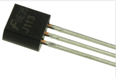
If the J113 were part of the diyAudio B1 Korg kit, then they should be ok.
You said that the preamp buzzed. Does it still buzz after you swapped capacitors? Were both channels buzzing or just the left channel?
Does the Korg tube light up?
You are getting good voltages at T7 and T8, but no reading at T5 and T6. That is strange. Is your meter autoranging or do you manually set the range? It should be about 0.6 VDC at T5 and T6 relative to Ground.
Your pictures are not very high definition so it is difficult to zoom in and examine the board. From what I can see it looks like some of the solder joints have either too much solder or not enough heat, or both. Then some joints look like they do not have enough solder. For instance, the left channel output wires at the pcb (signal and ground with yellow at the end of the wires) look like not enough solder.
FYI, I sent two B1 Korgs in FW chassis to BAF for distribution...
I dont know whether it is just one channel buzzing or both share the same problem. left channel has no music coming out.If the J113 were part of the diyAudio B1 Korg kit, then they should be ok.
You said that the preamp buzzed. Does it still buzz after you swapped capacitors? Were both channels buzzing or just the left channel?
Does the Korg tube light up?
You are getting good voltages at T7 and T8, but no reading at T5 and T6. That is strange. Is your meter autoranging or do you manually set the range? It should be about 0.6 VDC at T5 and T6 relative to Ground.
Your pictures are not very high definition so it is difficult to zoom in and examine the board. From what I can see it looks like some of the solder joints have either too much solder or not enough heat, or both. Then some joints look like they do not have enough solder. For instance, the left channel output wires at the pcb (signal and ground with yellow at the end of the wires) look like not enough solder.
left channel no sound at all
right channel 70% buzzing noise and 30% music I play.
The parts are either from diyaudio or mouser, so the quality are probably fine.
The Korg tube is lit up successfully.
I use autoranger to measure the reading.
Is it possible that my nutube is not functioning as it should br? having some kind of defect?
Last edited:
Hi guys, i have a rather odd problem with my preamp.
Problem is that there is a static noise (im 99.99% certain its grounding issue noise) when i touch the metal knob connected to the pot. BUT, here is the weird part, when pot is at 0-30% there is no noise, from 30-50% some noise, 50-70% even more noise, but when it goes to 100% noise starts getting lower, and at 100% there is non at all. Noise is only static buzz sound when i touch knob, no noise when im not touching it.
Second question:
Also i get micro phonic ringing in normal operation, but i do listen to it quite loud, i have installed the foam pad underneath the tube itself like in instructions, but i guess i got the not so good model, so i need more dampening, i was thinking to add more spongy material underneath the tube, and add a rubber ontop of the tube, would that suffice ?
Thanks.
check that pot case is grounded with case/audio GND
use ohmmeter
if it isn't, improvise to get it done
use ohmmeter
if it isn't, improvise to get it done
14071466d,Please measure the voltage across the following resistors of both channels:
- all R1
- 332K on either side of the Nutube
- 475R next to T5 and T6
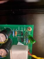
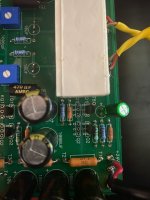
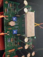
As mentioned previously, many of the solder joints do not look good, although I cannot tell for sure since the picture quality appears low when zoomed in. Good solder joints should be shiny and smooth. Many of your joints appear lumpy. The solder joints of the left channel output wiring appear to not have enough solder and perhaps not heated properly. Reheat all of the joints and remove some of the solder from joints that have too much solder, and reheat and add solder to joints that do not have enough solder.
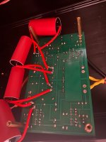
There is a lot to suspect here when I am looking at the soldering. One thing that stands out to me are the off board solder joints for the red Jantzen capacitors. In photo #14071466D, the lead of the capacitor on one side doesn't even look to be soldered. That would account for the no signal in one channel. What solder are you using? What solder iron are you using? I had the same results if the solder that I am using is very old and the resin is now bad. Makes it much harder.
Today I turned on my B1K and one channel is missing, it seems, that Nutube is broken ...
Pre was working since March without any problems ...

Pre was working since March without any problems ...


Both ...
obviously Dodo
most right filament moustache-halve is gone to travel inside of funny bulb, no more connected to incandescent island

- Home
- Amplifiers
- Pass Labs
- B1 with Korg Triode