I have tested / cross tested with my other preamp and two monoblocks, and with two sets of RCA-cables. I am quite sure, that the problem is in my soldering.
Power plus and minus are connected straight to the board, only 2pin DC IN connector in between (before the wall wart).
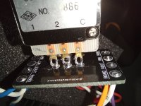
Going to buy 2 new switches and solder both again (on/off and selector).
Power plus and minus are connected straight to the board, only 2pin DC IN connector in between (before the wall wart).
Going to buy 2 new switches and solder both again (on/off and selector).
Attachments
-
 10-Pot-1.jpg312.6 KB · Views: 120
 -
 12-pot.jpg271.2 KB · Views: 125
 -
 13-pot.jpg302.3 KB · Views: 121
 -
 14-pot.jpg423 KB · Views: 120
 -
 15-pot.jpg474.1 KB · Views: 120
 -
 19_switch.jpg528.7 KB · Views: 126
 -
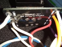
 Signal-OUT.jpg353.3 KB · Views: 122
 -
 power.jpg357.1 KB · Views: 117
 -
 Triode.jpg279.8 KB · Views: 120
Last edited:
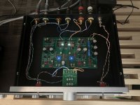
I finally built the kit I bought in 2020! Worked first try and sounded pretty good! Then I read the instructions and saw the initial start up section. Oops. My voltages were around 16V initially and I have them at 9.5/9.51 on each side.
I was using a Marantz 2250B receiver as a preamp so compared to that this sounds pretty good. I'm using a Fosi Audio X2 phono preamp with the Riverstone Audio tube upgrade with both. I swapped in the ACA I built a few years ago but it doesn't have enough grunt to power my tower speakers. I have an updated ACA kit that I'll have to build and try running two of them bridged next. The lone ACA sounded pretty good but the bass was pretty flabby.
When I rap on the top I definitely get the ringing but haven't noticed it from listening to music. Wondering if I need to put something on it or just leave it. Does it get hot? Kinda wish the case could have been designed to show off the cool blue Nutube lights but whaddya want for DIY?!? :>
All in all it was a great kit and a great experience.
Attachments

Eagle eyes... +1 on Ben Mah
And inded CD940 don't have a direction, nor does the suffix can be the culprit
Very likely something is not wired or soldered correctly sides volume pot / connections / selector...
Needs some time to resolve but no drama... Good luck!
Claude
And inded CD940 don't have a direction, nor does the suffix can be the culprit
Very likely something is not wired or soldered correctly sides volume pot / connections / selector...
Needs some time to resolve but no drama... Good luck!
Claude
Question, should I have continuity from boards +24V to all GND points around the board, when it is not even connected to the electricity?
I started with fixing those "picture obvious" problems (no help) and cleaning some other dirty connections here and there (no help), then...
I rebuild totally new selection switch (no help). I rebuild Pot with new pcb (no help). I removed pot and pcb (no help). I removed 2nd Input (no help), I removed newly built selection switch (no help). I can still hear my one channel, other channel is hum/buzz.
...and finally, I took power cables off the board and I still get that continuity from +24V to all GND points. Do I have a shortcut hiding somewhere?
No. That means you have an unintentional short. Even if it's connected to electricity you should have resistance between +24V and GND. With that said... I don't recommend measuring resistance with power to the unit.Question, should I have continuity from boards +24V to all GND points around the board, when it is not even connected to the electricity?
Edited to add - Removed the word "high". I don't know what your meter registers for continuity... and "high" is relative. My B1 Korg measures ~120 ohms from the +24V to the GND pad right next to it if that helps.
Last edited:
Ok, all power off, I get 119ohm, so it is not the problem for missing/humming/buzzing channel and I dont have a short circuit! Thanks you for that!
So what are the exact issues? Is it still one channel works but the other doesn't, and when you switch input RCA cables, then the other channel works and the channel that previously worked then doesn't work? If that is the case, that points to a bad source.
I had previously asked (post #8300) to try another source. You replied, "I have tested / cross tested with my other preamp and two monoblocks, and with two sets of RCA-cables. " Exactly what did you do?
Please tell us exactly what is working or not working. If you switch left input RCA cable to right input, does the same channel still work or does the other channel now work? What happens if you use the other set of inputs on the preamp?
Recheck all voltages at the various test points. Are they to specifications?
New pictures of new parts showing wiring please.
I am getting lost, but getting there eventually...
I got totally new RCA cables, to verify my other cables (no help).
I simplified my wiring on the board to a bare minimum (no help).
Voltages still same as originally:
T1=23.97V
T2=23.22V
T3=22.48V
T4=9.20V
T5=0.663V
T6=0.667V
T7= 9.51V (after small adjust)
T8= 9.51V (after small adjust)
I continued to simplify (and to remove possible culprits) from my "test setup", I did the following:
1. I connected new RCA cables from my DAC to Preamp Inputs (then power on).
2. I started playing sine signal from the PC to preamp through DAC with low volume.
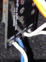
3. I measured left L IN to closest GND = 0.258V
4. I measured right R IN to closest GND = 0.259V
Seems to me that preamp is getting low level signal to both channels at the same voltage (AC) from the DAC.
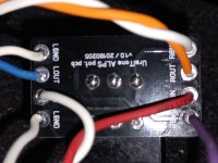
5. I measured left L OUT to closest GND = 1.638V (is this normal level of amplification?).
6. I measured right R OUT to closest GND = 0.000V
Right channel seems to be "dead", but both triodes are lit.
I also measured all my RCAs from "the free end" to the PCB, and got 0 ohm for short cables, and 1 0hm for 5.5m cables.
This seems to prove that RCA cables, connectors and wiring to and from the board are ok.
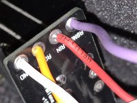
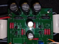
Then I started to look my Jfets, since what I have measured from the board, it seem to have similar values in both sides.
Left channel side works, and I can read from Jfet's that there is always "FKH33 + WH44 with J113" side by side. But...
From the right channel side I can read those same markings only from the "first row", where the inputs of the board are.
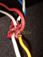
I can't read what those Jfets say, which are close to triode and are on the right side ("dead" side).
I must have cleaned those with electronics cleaner by accident, when I was cleaning the board (strange that others are almost intact).
Is it possible that I have soldered those by mistake in "opposite locations"? Would it explain this behavior?
Tiny white lines in the pictures are cotton from my cleanings, not wires.
I got totally new RCA cables, to verify my other cables (no help).
I simplified my wiring on the board to a bare minimum (no help).
Voltages still same as originally:
T1=23.97V
T2=23.22V
T3=22.48V
T4=9.20V
T5=0.663V
T6=0.667V
T7= 9.51V (after small adjust)
T8= 9.51V (after small adjust)
I continued to simplify (and to remove possible culprits) from my "test setup", I did the following:
1. I connected new RCA cables from my DAC to Preamp Inputs (then power on).
2. I started playing sine signal from the PC to preamp through DAC with low volume.
3. I measured left L IN to closest GND = 0.258V
4. I measured right R IN to closest GND = 0.259V
Seems to me that preamp is getting low level signal to both channels at the same voltage (AC) from the DAC.
5. I measured left L OUT to closest GND = 1.638V (is this normal level of amplification?).
6. I measured right R OUT to closest GND = 0.000V
Right channel seems to be "dead", but both triodes are lit.
I also measured all my RCAs from "the free end" to the PCB, and got 0 ohm for short cables, and 1 0hm for 5.5m cables.
This seems to prove that RCA cables, connectors and wiring to and from the board are ok.
Then I started to look my Jfets, since what I have measured from the board, it seem to have similar values in both sides.
Left channel side works, and I can read from Jfet's that there is always "FKH33 + WH44 with J113" side by side. But...
From the right channel side I can read those same markings only from the "first row", where the inputs of the board are.
I can't read what those Jfets say, which are close to triode and are on the right side ("dead" side).
I must have cleaned those with electronics cleaner by accident, when I was cleaning the board (strange that others are almost intact).
Is it possible that I have soldered those by mistake in "opposite locations"? Would it explain this behavior?
Tiny white lines in the pictures are cotton from my cleanings, not wires.
Attachments

Please take Ben Mah’s advice and check proper functionality of your signal source first. Either plug in another signal/source device using your new RCA cables AFTER checking their integrity; or plug the source into another system to check signal output on both channels.
Please follow the systematic approach suggested. It exists to rule out issues in a systematic way.
Please follow the systematic approach suggested. It exists to rule out issues in a systematic way.
Shot in the dark but... is it possible that your inputs are crossed up. Such as right channel input one goes with left channel input 2. been there done that.
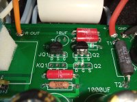
OK, it looks DC Voltages are good, AC signal gets to left and right inputs on the board. Signal does not appear at the right channel output.
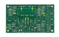
With signal going to both channels, measure AC Volts relative to ground at the following marked locations at both channels:
With signal going to both channels, measure AC Volts relative to ground at the following marked locations at both channels:
Attachments
1) 0.06V (Left) ; 1000 ohm
1) 0V (Right) ; 1003 ohm
2) 0.06V (Left) ; 1.9M ohm
2) 0V (Right) ; 2.3M ohm
3) 0.381V (Left) ; 1005 ohm
3) 0V (Right) ; 1003 ohm
4) 0.393V (Left)
4) 0V (Right)
5) 0.393V (Left)
5) 0V (Right)
After that i swapped RCA's around, no change in AC voltages. Right side still 0V from those points.
Left JQ1 S = 0.06V
Right JQ1 S = 0V
Left JQ2 D = 0.06V
Right JQ2 D = 0V
Same with other right side jfet; 0V. Left side gives voltages.
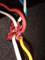
Input capacitor on the right (dead) side had broken wire inside the double layer of PTFE sheath.
Thank you all so far, this might not be over yet 🙂
But the music is already playing from the both channels.
Thank you all so far, this might not be over yet 🙂
But the music is already playing from the both channels.
Last edited:
The signal didn't get very far. It stopped at the first component in its path. So mystery is solved.
Enjoy the music. 🙂
Enjoy the music. 🙂
Hi all I am currently finishing the B1, and I would like to have 2 outputs, so a pre out output in +, with if necessary a preamp module to "support" the 2nd output. So my question is: How many usual inputs (50kohm) can be connected to the exit of the B1 without problem? or, what is the output impedance of the B1? Thank you if you have the answer!
Hello all... another guy asking for help here. I built up my B1 Korg last December but it was not working at completion. I haven't had time to get back to it until now due to a new baby. It passes the PSU tests, 23.8v and 9.2v. But, no sound and the nutube doesn't light up. So I've got power to the board but there is an issue somewhere on the board.
I have repaired many guitar amps and built up a slew of guitar pedals, but those all worked out of the gate and never had to trouble shoot. I am not sure how to go get started on finding the fault. I've read through the forum for insight but would appreciate some advice on next steps on how to find the fault and fix it.
What would be my next step?
you advice and time is very much appreciated... I have a power amp that is just begging for this preamp to work.
- Home
- Amplifiers
- Pass Labs
- B1 with Korg Triode