Whoa, music? Well, I will do some more 'rehab work' before I will test it. Got some transistors on the way just in case thanks to Elwood625. He had extras and was very generous. Anyway, I am so glad that this was simple (obvious). I will assume that everything at this point will just as easy to get it up and running tunes.
Are you sure the J113s are toast? The J113 CCSs seem to be working properly, with a current of 6.5mA (Post #8243, Post #8244).
You can try adjusting the pots for the proper voltage at T7 and T8 and see if it works.
You can try adjusting the pots for the proper voltage at T7 and T8 and see if it works.

🤣☕I don't know whether to laugh or cry but THANK YOU! Am I that far gone? Ok, putting the ballpeen hammer back on the shelf now. It (the answer) was right in front of my freaking face. I may have to turn in my driver's license and voting card in the morning. Thank you for your patience. You saved a couple of circuit boards from getting smashed.
Hi everyone,
Great project! finally got to it.
Mine sounds fantastic, and i am having fun with the bias and the sound character.
With the bias matched at 10.0V &
I have trimmed the 2 475 resitors each to less than an ohm of target
My test voltages a@ T5, 6 are 0.7028 & 0.7351, are these close enough?
Is the variation due to tolerances with the tubes?
Dave
Yes, there are some tube variations, which is why the trim settings are nominal. If you want great precision in the gain and/or distortion you have to measure and adjust for those.
On the other hand, precision is not what this is about...
On the other hand, precision is not what this is about...
Thanks for reply, Papa. I am intrigued by the process to finding and manipulating the distortion figures and may invest in an analyzer as I have other solid state and tube components that would deserve similar attention. This all started for me me with the F5 and the B1 & B3 which this is replacing. I think I have to do some testing and measure the gains before I go further. It all passed the initial listening test and I am not too picky/impressed by measurements but there is something ‘qualitative’ worth appreciating more. I guess I want to know more about the operating points elsewhere in my system.
Hi everyone,
Great project! finally got to it.
Mine sounds fantastic, and i am having fun with the bias and the sound character.
With the bias matched at 10.0V &
I have trimmed the 2 475 resitors each to less than an ohm of target
My test voltages a@ T5, 6 are 0.7028 & 0.7351, are these close enough?
Is the variation due to tolerances with the tubes?
Dave
Hah, your ahead of me. After misreading 475 multiple times, it had to be pointed out directly. And then, like you, I found a couple of resistors last night that both measured at 475 OHMS. Further, I ordered 25 more 1% resistors (Vishay CMF55) so that I would easily be reminded next time to get it right the first time. Your voltages look almost the same as mine which are at .75 & .74 respectively.
Will this circuit work with a bipolar power supply? If yes, please let me know how to wire for this configuration. Thanks!
Hi!
I need some help. The left side of the Nutube lights up very very dim. The right side is a nice green.
I do not find the fault as both sides show equal values:
Resistance at the Nutube from F1 to F2 = 11.5 Ohms; From F2 to F3 = 11.5 Ohms - so I assume the heaters of both triodes are OK.
Voltage before the 475 (!) Ohm resistors is 9.2 Volts for both sides. Voltage at T5 and T6 is 0.67 V. So both heaters consume the same current but one side does not light up.
Which part of the tubes emitts the light?
I worked quite some times to find cold solder joints. Found some.
Any Ideas? Broken Nutube?
Yes, pictures please.
Did you try adjusting the pot to get the correct voltage at T7, T8?
The heaters seem ok. The dim glow is likely due to not enough plate current.
Did you try adjusting the pot to get the correct voltage at T7, T8?
The heaters seem ok. The dim glow is likely due to not enough plate current.
Hello
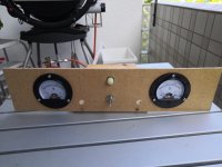
here are the pictures including the provisory front. I want it to look very retro with the pots sticking through the front.
And no I did not adjust T7 and T8. At T7 and T8 I have 19.6V. I tried to adjust T7 but I could not. As the value is so high I did not try to adjust T8. May be the potentionmeters are to old.
Attachments
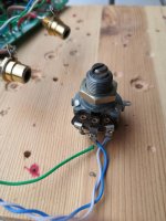
No picture of pots?
What are they? They appear to be off-board. Disconnect them and measure them to make sure they work.
Post picture of complete preamp, showing all wiring and parts.
What are they? They appear to be off-board. Disconnect them and measure them to make sure they work.
Post picture of complete preamp, showing all wiring and parts.
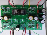
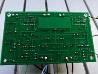
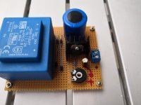
Here are more pictures.
I removed the potentiometers (Preh) from the circuit. With 9K8 and 9k55 they measure OK. They travel smooth.
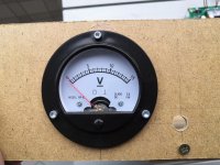
The power supply is nothing special. Just a basic LM 317 circuit. The meters are new bought from ebay.
I removed the potentiometers (Preh) from the circuit. With 9K8 and 9k55 they measure OK. They travel smooth.
The power supply is nothing special. Just a basic LM 317 circuit. The meters are new bought from ebay.
Attachments

Now that there are photos my thought is confirmed.
The left channel potentiometer is wired incorrectly, you have the blue and green wires reversed at the PCB.
Very easy to fix! 🙂
The left channel potentiometer is wired incorrectly, you have the blue and green wires reversed at the PCB.
Very easy to fix! 🙂
Capacitors are inserted correctly. Resistors I measured in the circuit. They are all the appropriate value (except the 270 Ohm resistor which measures 150 Ohms in the circuit but is clearly marked 270 Ohms). The R's supplied with the transistors measure all the same about 92 to 95 Ohms in the circuit.
Transistors are Fairchild. So I think they are in the right position. I bought them paired from the diyAudio store. When I checked them with my cheap transistor checker, three of them were nearly the same, one measured differently. They are not shorted
16.9 V at T7 and T8 seem like the same problem in both channels. How can I proceed?
- Home
- Amplifiers
- Pass Labs
- B1 with Korg Triode