I changed the wiring of the potentiometer. Switched the unit on for a short time. Independent whether I turn the potentiometers clockwise or conterclockwise T7 and T8 jump to more than 15 Volts (the maximum of the voltmeters on the front s 15 V).
How can I proceed? What to check?
How can I proceed? What to check?
So regardless of which way you turn the pot, the voltage jumps to 15V? That should not be. What voltage does it start at before you turned the pot?
Disconnect the pot and measure the resistance between the middle and side connections on the pot. When you turn the pot does the resistance increase in one direction and decrease in the other direction? Repeat with the middle and other side connection. Confirm that the pot is functioning correctly.
Disconnect the pot and measure the resistance between the middle and side connections on the pot. When you turn the pot does the resistance increase in one direction and decrease in the other direction? Repeat with the middle and other side connection. Confirm that the pot is functioning correctly.

I changed the wiring of the potentiometer. Switched the unit on for a short time. Independent whether I turn the potentiometers clockwise or conterclockwise T7 and T8 jump to more than 15 Volts (the maximum of the voltmeters on the front s 15 V).
How can I proceed? What to check?
Listen to this guy. He saved my butt only a few days ago with a different problem with this circuit that I caused that I was sooo sure that I didn't make a mistake.
Hi Ben, Hi 6L6
I have to report a small wonder!
I removed the potentiometers again from the circuit. They tested flawless. Connected them again. Removed the meters from the circuit and reflowed some solder joints.
Before starting up the circuit I adjusted the potentiometers so that there was maximum resistance between earth and grid. Which means minimum resistance From B to grid. And it happened!
1. Now both sides of the Nutube light up in a nice green (before only one side lighted up).
2. I am able to adjust T7 and T8. They were 5 and 7 V.
As I have a family event today I did not go further. I am so happy!
Many thanks for your help!
Hi 6L6
At the moment I use a passive preamp from Khozmo (shunt regulated) which is really transparent. I will attach the Nutube behind it using the Khozmo as source / volume control. If in this combination it sounds better I will make a nice enclosure and send photos. If not, it was anice experiment. So press your thumbs.
At the moment I use a passive preamp from Khozmo (shunt regulated) which is really transparent. I will attach the Nutube behind it using the Khozmo as source / volume control. If in this combination it sounds better I will make a nice enclosure and send photos. If not, it was anice experiment. So press your thumbs.
Hi Ben Mah
Solder pads on the PCB have become so tiny that cold solder joints were a nightmare to me with this project. Otherwise without your propositons I would have given up. Thanks.
Solder pads on the PCB have become so tiny that cold solder joints were a nightmare to me with this project. Otherwise without your propositons I would have given up. Thanks.
Good news! Both channels working. I have it in the small system between tuner and preamp (Toshiba Aurex) feeding Infinity infinitesimal IV via Quad 303. Sounds much more lifely.
I just got the B 1 and I have (2) 10 uF Sonicaps on hand. Which position of the (6) 10 uF capacitors would benefit the most from the Sonicaps?
Also is it possible to add a motorized remote volume control? If so which one would you recommend?
Thanks
Scott
Also is it possible to add a motorized remote volume control? If so which one would you recommend?
Thanks
Scott
Boards have arrived. I removed the filter part from the main board, as it is as small as can be like this, and you can see my smd version of marks p089zb filter. In general, very tiny indeed. Rest of the parts are on their way.


I have 2 stereo RCA Inputs and 1 stereo RCA Output. One channel is "dead" with hum/buzz. Also hum/buzz, when I touch chassis.
Triode lights up normally.
What I have measured, all seem ok from the both channels. Similar numbers from both sides.
If I change RCA inputs to opposite (right to left and left to right), this changes "dead channel" to work. Problems moves with Input RCA cables.
I tested that with PC, which sends sound only to left or only to right channel. I can hear "Left channel" and "Right channel", but not at the same time.
There is always hum/buzz on the "dead" channel.
So, preamp board itself seems to work ok for both channels, but only separately (+ the hum in the other "dead" channel).
To make this a bit more complex, I have added some mods.
-SMPS DC Filter P089ZB Kit
-"GlaudeG" bigger capasitors onboard
-Input, coupling and output resistors located outside of the board
-1Mohm extra resistors between negative and positive of all those Input RCAs; 4x 1M resistor for 2 stereo RCA Inputs).
-TKD 2P-2511S 10k stepped stereo potentiometer with local connection board, made for Alps RK27 (6 holes in / 8 out; 2x GND for both channels).
On board between +24 and GND = 23,96V (same with all ground points).
BUT also connection between GND and R IN and L IN, so R IN and L IN are connected. Should those be like that?
T1 = 23,96V
T2 = 23,22V
T3 = 22,47V
T4 = 9,23V
T5 = 0,667V
T6 = 0,679V
T7 = 9,51V
T8 = 9,51V
R1 = 0,913V (right)
R1 = 0,964V (left)
Both channels of Nutube light up.
But no right channel output (only hum), changing input channels, "dead" channel works.
Working channel sounds normal.
JQ2 = 10,63V (right)
JQ2 = 10,59V (left)
JQ1 = 21,20V (right)
JQ1 = 21,19V (left
JQ2 = 9,53V (right; close to triode)
JQ2 = 9,52V (left; close to triode)
JQ1 = 21,20V (right; close to triode)
JQ1 = 21,19V (left; close to triode)
From all RCA Input grounds, I get connection to all ground points. But also to R IN and L IN.
From RCA Output grounds, I get connection to all ground points. But also to R IN and L IN.
Potentiometer 0%:
-All GND connects to all other GNDs.
-GND connects also to ROUT and LOUT (and from ROUT to LOUT).
Potentiometer 100%:
-All GND connects to all other GNDs.
-ROUT and RIN connects.
-LOUT and LIN connects.
I have tried to follow this to get help, but it is getting really hard to follow:
https://www.diyaudio.com/community/threads/b1-with-korg-triode.313612/page-393
RCA Input connected to the RCA Output with the RCA cables and volume pot turned 100%, I measured AC voltage relative to GND:
Not sure if I did these correctly...
GND to R IN = 0V
GND to R GND = 0V
GND to L IN = 0V
GND to L GND = 0V
GND to JQ1 D = 0V (left)
GND to JQ2 D = 0V (right)
1) GND to R IN = 0,02V
1) GND to L IN = 0V
2) GND to 1K left = 0V
2) GND to 1K right = 0,5V
3) GND to 332K left = 0V
3) GND to 332K right 0,13V
4) GND to 33.2K left = 0V
4) GND to 33.2K right = 0V
Simple tests to find the problem (or to narrow it down)?
How to remove hum/buzz? Am I missing some grounding? My DC IN is with 3 connectors, but only two connected. Third to GND also?
At the beach but very quickly...
Whatever, probably a short between signal path and ground, or a ground missing... if both channels are working when fed independently it sounds quite promising and not necessarly a problem at B1K board (other than input and output wires) to investigate first?
Quote: If I change RCA inputs to opposite (right to left and left to right), this changes "dead channel" to work. Problems moves with Input RCA cables.
=> Sounds like the problem is either the RCA cable or your source, not B1K. Have you tried with another source and cable?
You also said Rin and Lin etc. were shorted to ground, which is defo not normal. Did you measure that with the RCA cable plugged in? Odd did you measure that while the B1K was connected to nothing (neither inputs nor outputs)?
More knowledgable persons will for sure step in and ask also for pix
Good luck!
Claude
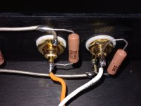
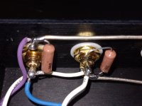
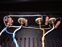
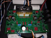
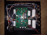
Please post pictures of everything. Include wide shots showing the whole preamp with board connected to RCAs, and closer shots of the RCA jacks and wiring.
It sounds like a wiring error.
It sounds like a wiring error.
I think my cables and other components are ok (cross tested). It is this "almost ready" preamp, which is still giving some problems.
Changed my DC IN connector to 2-pin version. It helped with the most of the hum/buzz. Maybe I should have connect the third leg to GND?
I removed extra filter for power and also the on/off switch to simplify search. No change in behavior.
I noticed that my input capacitors are not exactly same. Both should be 598-940C8P22K-F (that is what I ordered), but those have small difference in packaging:
940C10P22K-F .22MFD +-10% 1000VDC.CDET MW
940C10P22K-F .22MFD +-10% 1000VDC.CDET AV
Is it possible that MW/AV is making a difference? Or could it just be a manufacturing batch code?
Coupling capacitors: 598-940C6W1K-F
Output capacitors: 598-940C6W3P3K-F
Do I need to worry about "direction of those" capacitors? I don't see any markings that those should be connected in one certain way.
Attachments

Capacitors are not polarized so direction is not an issue. Markings not an issue.
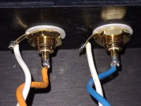
DC in connector is not visible so cannot comment. However DC power is + and - so only two wires, therefore only two power wires to connector and to board.
Cannot see wiring details of wires to input selector switch, from selector switch to volume pot, and volume pot to board. You should study the build guide and make sure that you have done the wiring correctly.
B1 Korg Build Guide
Post pictures of the wiring to the input selector switch and volume pot.
If one channel and then the other channel works if inputs are flipped, have you tried another source? Have you tried the source on another preamp to confirm the source has two working channels? Do you have another source that you have confirmed to have two working channels that you could connect to the B1 Korg?
- Home
- Amplifiers
- Pass Labs
- B1 with Korg Triode