
Well done!
May I ask what caps you used in the signal path? Those 6 tiny black bricks...
Thanks
Claude
May I ask what caps you used in the signal path? Those 6 tiny black bricks...
Thanks
Claude
I looked up this capacitor and it seems to be a surface mount unit. Can you describe how you adapted it for use in a normal PCB?Thank you.
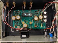
That's Rubycon pmlcap 10uf.
I am betting that there are different 'packages' for this cap. When I look for parts, I am frequently frustrated by seemingly endless options such as this, even when I hope that the filtering would avoid most of that sort of thing.
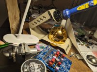
Well, that didn't take long. Looking for these caps, I came to the conclusion that they are only offered as SMD. The good news is that I looked at Tamra's photo closer and noticed that there was a lead soldered to each end of the cap that then stuck through the circuit board hole. Pretty ingenious.
Well, that didn't take long. Looking for these caps, I came to the conclusion that they are only offered as SMD. The good news is that I looked at Tamra's photo closer and noticed that there was a lead soldered to each end of the cap that then stuck through the circuit board hole. Pretty ingenious.
Last edited:
I thought that might be the case, but having never used SMD, I wonder how how he got the leads soldered in without melting the solder attaching it to the SMD cap or vice versa). However it was done, Tamra's technique is enviable!
I share you concern! I was thinking the same thing, and SMD usually offer little to no surface to begin with. Just a guess, but with very steady hands and some sort of clips to hold stuff in place, I might be able to get it done. I would rather have the leads to begin with. The wave of the future is upon us.
Deals like this could be found in the “good old days” when there was a large number of parts and components manufacturing in the US. Surplus stock would be sold to small, independent dealers who would then sell to smaller companies and hobbyists. That surplus market is much reduced, sad to say.
For a while now i was feeling that this project is ripe for smd version, and i had an itch yesterday and drew it up. Semi smd, caps are trough hole (nichicon uhw are unbeatable for this preamp, 1800uf, so almost double capacity) and 5W 270R resistor, still not feeling like leaving my fingerprints on it 😅 Coupling caps are MU (acrylic film) as @tamra used in his build, i'm a big proponent of that cap, really really good for such a small little bugger (but can leave a pad for 10uf silmics if someone prefers them over film). Jfet buffers are jfe2140, factory matched, good and cheap (no need to get many to match, wasting time and money). I've included Mark's smps filter on board, but i'll probably remove in final version as my smd version of it is such a small footprint it can easily fit on the side of the case. Only benefit here is bigger cap for the smps filter, which can improve performanse, but can also trigger some smps supplies to not start, so i find regular 470uf uhw pair are enough. Current dimension is 65x80mm, drastically smaller, and it will be even less in final version. Another benefit of smd is ground pour (plane). I'll be designing a flexi connector for nutube itself to isolate it from board as well. As usual, i'll build and test first, then leave files here like with my previous custom b1k board.

Thank you but It's not that difficult if you have fire metal and good solder iron.Ugh and double ugh. A friend who is a professional I. This regard said that DMD tweezers were the right thing to use for SMD removal and placement. He also uses large magnifier.
Pmlcap is fatty so quite large area to solder.
Attachments


- Home
- Amplifiers
- Pass Labs
- B1 with Korg Triode