If the voltage at T5, T6 are at or about 0.6VDC, the filament should be good.
If voltage at T7, T8 can be adjusted to about 10VDC, the Nutube should be good.
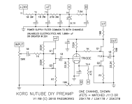
Check that the resistor at output to ground is 33.2K and not a much smaller value.
Measure the voltage across R1 of both channels. If the JFETs are good, voltage should be the same at both channels. There are two R1 resistors in each channel.
Some good pictures may be helpful.
If voltage at T7, T8 can be adjusted to about 10VDC, the Nutube should be good.
Check that the resistor at output to ground is 33.2K and not a much smaller value.
Measure the voltage across R1 of both channels. If the JFETs are good, voltage should be the same at both channels. There are two R1 resistors in each channel.
Some good pictures may be helpful.

I am only putting this out there to say yes, one of these mechanical controls would be a great idea. I recently used one in a project. The price of $120 is prohibitive for this project though. On the plus side, it obviates the need for a balance control.Me too, love my new B1 but I still don't have a balance control! Could one substitute a clutch-ganged volume knob?
Attachments
T5 and T6 match perfectly and are around .654VIf the voltage at T5, T6 are at or about 0.6VDC, the filament should be good.
If voltage at T7, T8 can be adjusted to about 10VDC, the Nutube should be good.
Check that the resistor at output to ground is 33.2K and not a much smaller value.
Measure the voltage across R1 of both channels. If the JFETs are good, voltage should be the same at both channels. There are two R1 resistors in each channel.
Some good pictures may be helpful.
Both T7 and T8 I set at 10V
I measured across all R1 and all are the exact same measurement.
I took the board back out. Reflowed solder and cleaned the bottom with alcohol. Still no sound on the right channel.
I also retested all resistors and compared them on both sides. All measurements match up.
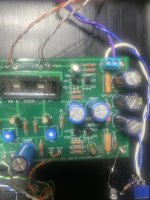
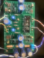
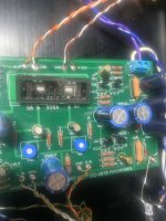
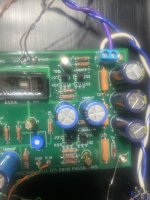
Pictures?
Swap Left input and Gnd wires at board with Right input and Gnd wires and see what happens.
Swap Left input and Gnd wires at board with Right input and Gnd wires and see what happens.
Dang. The pictures I took look terrible.
I did observe something while checking voltages. I noticed the top right Gate/Source voltage is .1V higher on the right than the left.
Not sure if that could be an issue.
I will try swapping the grounds but not sure that would work. I ended up soldering them all together at the pot to see if that would get the right channel working.
Attachments
The pictures do look terrible. I can't see much.
I suggested swapping both the INPUT and GND wires of the good left channel at the board to the right channel INPUT and GND at the board.
I suggested swapping both the INPUT and GND wires of the good left channel at the board to the right channel INPUT and GND at the board.
I’ll take some new ones tomorrow.
I think I tried swapping the input and gnd wires like you mentioned already, but I’ll try it again to be sure.
I think I tried swapping the input and gnd wires like you mentioned already, but I’ll try it again to be sure.
Another check: with the power off, and all input and output wires in place, measure the resistance between Input+ and Ground at the board and also between Output+ and Ground at the board.
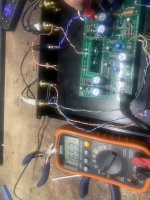
Ok. Here are the tests I tried this morning:
Flipped the inputs after the pot. No change the right channel still doesn’t have sound.
I switched the grounds and resoldered them. No change.
At the board inputs I’m seeing 0 ohms for both.
At the board outputs I’m seeing 33k for both.
I am also seeing the same results at the rca jacks too.
Flipped the inputs after the pot. No change the right channel still doesn’t have sound.
I switched the grounds and resoldered them. No change.
At the board inputs I’m seeing 0 ohms for both.
At the board outputs I’m seeing 33k for both.
I am also seeing the same results at the rca jacks too.
Attachments
I didn't remember at first, having this problem, but a few years ago, one channel was out. I swapped tubes (yah, not that easy because of the soldering involved), and bingo, was back in business. I have read issue after issue with these tubes, and when they work, they are great.
0 Ohm at input is not good. I am surprised that the good channel is also at 0 Ohm. Was the volume pot at minimum volume? Set the volume pot at maximum volume and re-measure.
I tried that too. Both sides showing a little under 50k ohm with volume pot at the max at the inputs.
Connect a source to the preamp, no amplifier connected to preamp output, power up source and preamp, multimeter set to AC Volts, check for AC Volts at preamp board input, at 1k resistor after input capacitor, at 33.2k resistor at Nutube grid, at 1k resistor at triode anode.
Volume pot need not be set at maximum. Set volume high enough so that the signal is able to be measured.
Volume pot need not be set at maximum. Set volume high enough so that the signal is able to be measured.
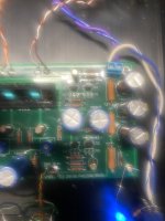
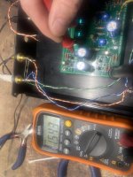
Attachments
Last edited:
Ok. Just made these measurements. Both the 1K resistors checked danced around even with the volume at 0. Both the inputs matched.
But, the 33.2K resistor had a big difference.
The left side with my volume halfway was around .45V and changed with the input music playing. The right side was close to 0V and didn’t change with the music.
But, the 33.2K resistor had a big difference.
The left side with my volume halfway was around .45V and changed with the input music playing. The right side was close to 0V and didn’t change with the music.
Previously you had measured the voltage drop across the R1 resistors and voltage was present and equal. So that says to me that current was flowing through the JFETs and that the JFET CCSs were working.
The bad VAC reading at the right channel 33.2k resistor at the tube grid indicates no signal at that point. So either the preceding capacitor is blocking the signal or the JFET buffer before that is not passing the signal. So Q1 at the input is suspect. But recheck the voltage across the R1 resistors. What is the voltage?
Also check the solder joints at the 10uF capacitor adjacent to the tube.
Good news. I pulled out the 10uf cap and it appeared the trace had been removed from someone de-soldering so that cap didn’t have a good connection. I made some solder bridges to connect the pads in circuit and that fixed it!
I should have mentioned I bought this kit fully stuffed with the exception of the Nutube. I can only guess the builder had put some nicer 10uf poly caps on it but removed them and put some smaller electrolytic 10uf caps back in.
Only slight problem I noticed after pausing the music was on the right channel the Nutube just kept ringing and wouldn’t stop. I turned the unit off, then back on and no ringing. Not sure what would have caused that. I’ll play it again tonight on my secondary setup to see if the ringing continues.
Simple as that was, it is still a sneaky problem! I have been guilty of 'trace damage' more than once.
One thing that I would recommend is not to rely on just a solder bridge for your connection. Some sort of fix that involves at least a copper wire in place of the solder bridge would be a better outcome.
One thing that I would recommend is not to rely on just a solder bridge for your connection. Some sort of fix that involves at least a copper wire in place of the solder bridge would be a better outcome.
Yea. So crazy it was just a cap needing to be fixed.
I used a piece of a resistor leg I had cut to connect the two traces. I’ll find a piece of copper wire to swap in if recommended.
I’m going to try. To dampen the whole preamp to fix the ringing. I had the top off as it on my work bench when it had the continuous ring
I used a piece of a resistor leg I had cut to connect the two traces. I’ll find a piece of copper wire to swap in if recommended.
I’m going to try. To dampen the whole preamp to fix the ringing. I had the top off as it on my work bench when it had the continuous ring
- Home
- Amplifiers
- Pass Labs
- B1 with Korg Triode