Papa Nelson,
I don'tknow what is the maximum output impedance I can accept. I am using different power amps with input impedance from 10k to 22k. (Heed Canopus 10K, Heed Obelisk 22K). I am thinking about building two ACA (bridged monos).
How much gain i want to lose ? If -3dB will be not enough, than -6dB.
🙂
I don'tknow what is the maximum output impedance I can accept. I am using different power amps with input impedance from 10k to 22k. (Heed Canopus 10K, Heed Obelisk 22K). I am thinking about building two ACA (bridged monos).
How much gain i want to lose ? If -3dB will be not enough, than -6dB.
🙂


Papa Nelson and Zen Mod thank you so much for your help 🙂
Yes, of course Kiloohms, not Ohms 🙂
One more question - I was reading a lot about B1K and 0,22uF at the input seems to be enough (I had one left from some speaker project).
Is it really enough, or should i better take 1uF or more ?

Yes, of course Kiloohms, not Ohms 🙂
One more question - I was reading a lot about B1K and 0,22uF at the input seems to be enough (I had one left from some speaker project).
Is it really enough, or should i better take 1uF or more ?
if you read it's enough, that's it
whoever wrote that, probably gave calculus to confirm what's corner frequency
whoever wrote that, probably gave calculus to confirm what's corner frequency
Success!
Sounds great and loving how it plays with my setup. Thank you for the @Ben Mah for the help identifying my issue with the JFET. Also, thank you @ClaudeG for the details on your build. This was my first and won't be my last. I'm organizing leftover parts to put another one together for a second system. Fun Stuff!
Sounds great and loving how it plays with my setup. Thank you for the @Ben Mah for the help identifying my issue with the JFET. Also, thank you @ClaudeG for the details on your build. This was my first and won't be my last. I'm organizing leftover parts to put another one together for a second system. Fun Stuff!
Attachments
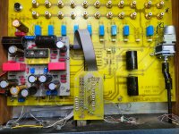
Is there a reason you placed different sized caps at the locations they are at or just randomly picked one of three "10uF" marked sites?Success!
Sounds great and loving how it plays with my setup. Thank you for the @Ben Mah for the help identifying my issue with the JFET. Also, thank you @ClaudeG for the details on your build. This was my first and won't be my last. I'm organizing leftover parts to put another one together for a second system. Fun Stuff!
Hi
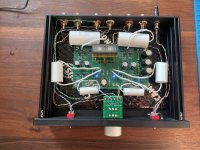
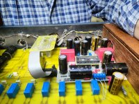
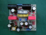
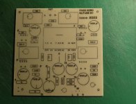
I am sending a few pics of my new NUTUBE B1. It is build on a PCB which was desighned by COREL DRAW.
Excellent sound, full of music, with very pleasand listening and much better than the DC B1 or my Grounded Grid tube preamplifiers. The power amps are two DIY Pass Aleph 30 monoblocks.
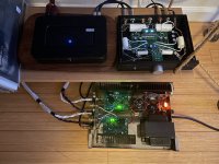
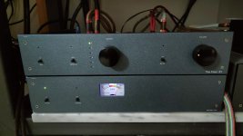
I placed the PCB on the mother board of my old AlephL and DCB1 enclosure and is powered by two (in series) 12v acid lead batteries .
I have a lot of 2SK389 on my shelf so as I made the pcbs for them and I also use MUNDORF 4.7 uF capacitors and WIMA MKP 2.2 uF parallel with
ELNA Silmic 10uF.
The T7,8 voltages was finally adjusted at 9.5V. After playing for more than 100 hours the voltages are remaining at 9.55-9.57 V .
Because of the 2SK389 I didn't use the R1 resistors.
I want to thank Nelson again for sharing his designs with the DIYAUDIO community all these years.
Kostas A. Vazakas
Egio, Greece
I am sending a few pics of my new NUTUBE B1. It is build on a PCB which was desighned by COREL DRAW.
Excellent sound, full of music, with very pleasand listening and much better than the DC B1 or my Grounded Grid tube preamplifiers. The power amps are two DIY Pass Aleph 30 monoblocks.
I placed the PCB on the mother board of my old AlephL and DCB1 enclosure and is powered by two (in series) 12v acid lead batteries .
I have a lot of 2SK389 on my shelf so as I made the pcbs for them and I also use MUNDORF 4.7 uF capacitors and WIMA MKP 2.2 uF parallel with
ELNA Silmic 10uF.
The T7,8 voltages was finally adjusted at 9.5V. After playing for more than 100 hours the voltages are remaining at 9.55-9.57 V .
Because of the 2SK389 I didn't use the R1 resistors.
I want to thank Nelson again for sharing his designs with the DIYAUDIO community all these years.
Kostas A. Vazakas
Egio, Greece
Attachments


I’m currently trying to finish another one of these preamps, but no sound on the right channel.
All voltages check out and I confirmed all voltages on the good channel vs bad channel match.
I bypassed the input selector and pot and confirmed it’s not either of those
i bypassed the board on that channel and determined my output rcas are wired fine.
I reflowed all solder on that side.
I’m now thinking the tube could be faulty. Is there a way to check continuity?
- Home
- Amplifiers
- Pass Labs
- B1 with Korg Triode