Hello Nelson, I live in the UK, so if I float the earth on a DH Labs power cord that I will use with the Meanwell that should be OK, also if the B1 is not grounded why would I get a possible ground loop. Thanks.
Amendment: floating the earth ground on the plug is not a good idea, so I have looked up the Class ll of the Meanwell 24V 5A that uses a figure of 8 plug and go that way, would I have to change any resistors or change any values using the Meanwell with the Korg Nutube B1. Thanks.You only have to watch out for possible ground loops if the Meanwell shares its ground with AC earth and so does the source. You can get Meanwells with isolated ground as well as other brands.
Thank you, ordered a bunch of resistors today.I assumed in the above your source was indicating volume level in -XdB format. So 0 dB is the loudest, -XdB is attenuated.
On some products you may not have that, but something like a volume from 1 to 10 or to 100, 1 being low level, 10 high level (=loud). Or perhaps just a virtual rotary knob without any graduations at all on it! For the above, you really need to find out the required attenuation in -XdB format.
If that's not the case it gets more complicated. Not a real issue, but in case you may not dispose of measurement tools and some practice perhaps, things get a tad more complicated... No worries, in that case you could still do with a multimeter and say your good old volume potentiometer to determine your required fixed attenuation level.
There are other ways of course, but with some equipment, or software knowledge (depending on your source), I will anyway let much wiser people here guide you while it is bedtime this side of the world...
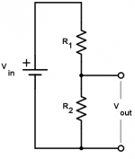
So if I understand correctly in practice with just a voltmeter I should put the old 50K pot back in the KB1 circuit, with volume maxxed out the Dac (there are no dB markings) and measure Vin and Vout at the pot at the loudest tolerable level? to get the R2 value of the divider?
Attachments
YES
Apart that you don't need to measure voltages, just leave the unit unpluged and without changing the pot position measure the resistance values.
You need to measure R1 and R2 as described. Well, if you know that your pot is a 50k pot, then once you have R1 you can easily deduce R2...
Once you have R1 and R2 you can either go for fixed resistors with exactly these values (or close to, as Rs don't come in any value)...
...or, should you want to change the impedance to something close to 20k (for example), go for R1B and R2B that are sclaed down from the previous ones (same ratio, that what matters) and respect "R1A+ R2B" = 20k (instead of 50k)
Goind that way enables a 20k pot (or close to 20k, or any value you wish depending on what resistors you have handy)
Good luck
Claude
The original design calls for a 50K input impedance. I will for for fixed values R1 20K and R2 30K total 50K, In reality, it should provide a wide range of digital volume adjustment.
Thanks again for the clarifications
Thanks again for the clarifications

Hmmm... you may want to read the entire thread.
I don't think the original design "calls" for a 50k input impedance. I think this has been given a std value / as rough baseline, as many other bits BTW. 50k is a no brainer inded, but indeed the B1K needs to provide some load on the other side so you can't play it silly. I am quite confident any value between 15k and 50k should work in this set up, if just considering trhe B1. Oh, and if considering any modern digital source - but well, this isn't making a lot of difference probaby to your ears anyway in terms of noise etc.,, so take any value around of 50k if you are confident with it.
All I want to say is that you have flexibility there: don't take 50k as a critical spec, on the contrary. NP commented on that in this thread if you don't trust me... You have a flexibility here and don't need round figures... comes handy when chosing existing Rs...
Now, if you take R1 and R2 as you said, that is going to provide you with a small attenuation in terms of dB, as these, as your ear+brain combo, aren't linear. I mean don't expect a massive change in terms of attenutation or volume pot psition... Me, I wouldn't even bother with these values, they are within your practical safety margin.
How did you end up with 20k and 30k if I may ask?
I marked a point pot where it is the loudest tolerable point with DAC volume maximum level; then took a resistance reading on pot of roughly 30K. Should provide me with the digital attenuation room / fine adjustment level that I am looking for.How did you end up with 20k and 30k if I may ask?
I'm using KB1 without pot. It's difficult to see on picture but I have one resistor between In and ground and one resistor in series with In (invisible in shrink tube). For each channel. This should be equivalent to a volume setting at 70%.

@sebdti
So that would mean there is little headroom, ie. if you have a (correct) log volume pot you were probably already past 2 O'Clock...
In that case IMHO little point in building a voltage divider, you are close to needing full pot amplitude...
Good luck either way
Claude
So that would mean there is little headroom, ie. if you have a (correct) log volume pot you were probably already past 2 O'Clock...
In that case IMHO little point in building a voltage divider, you are close to needing full pot amplitude...
Good luck either way
Claude
what R values are you using?I'm using KB1 without pot. It's difficult to see on picture but I have one resistor between In and ground and one resistor in series with In (invisible in shrink tube). For each channel. This should be equivalent to a volume setting at 70%. View attachment 1131588
perhaps will try 20K first no divider@sebdti
So that would mean there is little headroom, ie. if you have a (correct) log volume pot you were probably already past 2 O'Clock...
In that case IMHO little point in building a voltage divider, you are close to needing full pot amplitude...
Good luck either way
Claude
I guess you are familiar with that, but just in case of...
You do realise that 20k, or 30k, or 50k or "whatever Ohm" pot gives us just an info on its constant impedance as seen by the circuit upstream (source for you, the output of your DAC neglecting cable impact) and that has NO relationship whatsoever with the attenuation
(OK, being pedantic it has a small impact depending on the downstream circuits impedance, but let's not get into that detail, in our case it is quite independant of the attenuation).
In short a 20k log pot will give you the same overall attenuation range as a 50k pot roughly, what makes the attenuation is not the pot impedance but the position of the pot as it acts as a variable voltage divider...
Going for 20k Rs instead of your existing 50k Rs is likely to make no change at all to your ears (perhaps a very tiny less noiser, but quite pointless on a B1K IMHO).
Just to make sure there is no confusion on the expectations, but I guess you know all this already...
Before: 15k Ohm in series; 30k Ohm paralel.

After: 30k Ohm paralel only

No perceivable change in sound.
GGood to have tried though!
After: 30k Ohm paralel only
No perceivable change in sound.
GGood to have tried though!
Nice try and...No wonder
Sound quality probably identical (who can hear a single additional resistor simply put in the path without any other impact re frequency etc.?)
However soundlevel should be different, the -3.5dB or so attenuation is gone, so obviously plays a little bit louder.
Not a big attenuation though, I wouldn't bother indeed for such values in a variable volume configuration...
If interesting then the following, closing this nearly off topic discussion, albeit being one of the volume controls indeed fitted with the B1K in its same casing. at mine and being both DIYer friendly and increadibly cheap..,
FOR MY SET UP, but I found it worked quite OK for std hifi systems at friend's eventhough their gain chain and DAC were different, I used a 2 position attenuator switch based one the above mentioned voltage divider.
First position is 0dB (no attenuation, just impedance match loading), second position is -28dB. High gear and normal gear, I call them. Between these values and under I use the DAC's volume control when available of course.
I found that to my ears even 10y old DACs with digital volume controls didn't produce any noticeable sound degradation at -28dB, whereas some became slightly noticeable at higher values, although recent units à la D70S are "perfect attenuators" down to -34dB digitaly to my ears. Let's say a first range of 0dB to -28dB is on the safe side for most DACs while enabling any loud playing of low recorded music. Call it high gear. Of course I could still keep high gear all the time and go with higher digital attenuation, but there is better....
The second range goes from-28dB to mute. That what I use the most as on normal records listening to music reasonably loud I end up being at y max 0 to -3dB digitaly or so, while enjoying a good attenuation range. It means in practice I can attenuate a source such as D70S down to 28 + 34 = 62dB without hearing any sound degradation while having a very non expensive remote controlled volume control. Worst case I need to stand up for high gear when patying very loud or on very low recorded music.
And lower than -62dB? I can still attenuate digitaly without standing up but at the slight cost of digital control loss (to my ears, with 16 bit CD recording, might be different with HR but then I have a safety margin of 6dB with a D70S)... a slight degradation that I don't hear really because the music is playing so low that any reasonable audiophile listening to distinguish any loss isn't possible.
My bet is most standard systems with a 2V ish source, resonable gain chain and normal to somewhat higher efficiency LS in domestic rooms could probably accomodate these figures or anything close to them... For headphone listening it could be somewhat different but then again these values could be different and of course even a 3 pole switch could be accomodated to fit a large range of HP (efficiencies)... probably.
Enjoy music
Claude
Last edited:
Oh, and to get that 0dB / -28dB "2 position attenuator" in front of the B1K with a close enough to 20k input impedance, I went from memory for the follwing values for resistors (can be adapted depending on your prefered supplier and cost, should you "hear" resistors):
- 825 and 20kk
I let you find out where these "R1 and R2" fit correctly to have the desired voltage divider ;-)
Have fun
Claude
- 825 and 20kk
I let you find out where these "R1 and R2" fit correctly to have the desired voltage divider ;-)
Have fun
Claude
I've tried using the socket system you can buy for the Nutube (so no soldering is involved) but it's really a noisy connection. I gave up upon that concept. One of the best isolation techniques for the Nutube is Pete Millett's isolation mounting board. In my experience with building several varieties of these not soldering the tube directly into the PCB reduces noise & microphonic issues down to nil. JMHO. CheersI think that in the future I will put the tube in a socket. They are no fun to remove as the leads are far from sturdy. Also, mounting could be improved by isolation if a socket were not attached to the board.
Some of you have placed 10 turn pots on the rear panel of the pre. That seems to be a very good idea for those of us who always want to know 'the difference'.
Hi all, saw that the 4x100ohm resistors are 0.4W. i have in house spare zfoil charcroft i could use, by they are 0.25w. Better i Stick to 0.4w? Between stock 50k alps and 10k TKD cp 2511(also spare) ,i better stick with the alps standard impedance? My dac source Is 50ohm
Thanxs
Thanxs
- Home
- Amplifiers
- Pass Labs
- B1 with Korg Triode