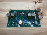
Hi, I have now desolder the failed Nutube.
Change the 470 ohms that was in the 475ohms spot with Dale 745 ohms.
Have been powered up now for one hour ( without Nutube in place, coming with post from RS later today ).
The readings I get is:
T1 = 24.02 vcd
T2 = 23.19 vdc
T3 = 22.36 vdc
T4 = 9.34 vdc
T5 = 9.34 vdc
T6 = 9.34 vdc
T7 = 20.31 vdc
T8 = 20.30 vdc
What do you think, solder in the Nutube? Frank

Thanks, I'll copy your idea!Hello jaaptina,
I put my 10kOhm pots to the backside of my B1 NUTUBE-pre.
Works nice.
Greets
Dirk 😀
Soundhappy: Tanx, now its playing again ( :
Frank
Congratulations
 Enjoy
EnjoyOpened chassis if you play music can bring microphonic high pitch sound.... It looks messy, but works well. [/ATTACH]
It's better to use something with closed on the top of the box..🙂 Best regards
Those voltages aren't off enough to cause the problem. What is the voltage across the 221 ohm resistors?
Hope it is not considered rude to come back to this.
I now have double checked all components on the PCB with no result. Polarities of capacitors and resistors values appear to be good.
The only finding I have is, that 2 of the J113s are labeled KH33, 6 are labeled KH35. Is this Okay too?
I followed the beautiful build guide very precisely. I am very sure, that I have not mixed up the bags with the matched transistors. The two KH33 are both in Q2 positions, so they came from the Q2 bag.
But again, do you know the voltage across the Source resistors of the constant current Source jfets?
As all R1s are connected to Q2s, I will refer to them by position on the PCB.
My voltages across R1 are:
Upper left 1.677V
Upper right 1.661V
Lower left 1.691V
Lower right 1.564V
Thank you very much! It is such a beautiful design, I would like to enjoy it.
My voltages across R1 are:
Upper left 1.677V
Upper right 1.661V
Lower left 1.691V
Lower right 1.564V
Thank you very much! It is such a beautiful design, I would like to enjoy it.
I hope that those are the voltages you have asked for?
I am a newbie. My background is computing, unfortunately not electrical engineering. So please excuse me.
I am a newbie. My background is computing, unfortunately not electrical engineering. So please excuse me.
Hello.
I recently created this preamp.
It sounds very good and I am enjoying it.
However, the gain is a bit high, which is inconvenient.
Where can I change the resistors to reduce the gain?
The standard gain is 16dB, but I would like to reduce it to about 10dB.
I am a beginner. I'm sorry.
I recently created this preamp.
It sounds very good and I am enjoying it.
However, the gain is a bit high, which is inconvenient.
Where can I change the resistors to reduce the gain?
The standard gain is 16dB, but I would like to reduce it to about 10dB.
I am a beginner. I'm sorry.
I've really tried finding the answer for this, but I can't find it.
It's probably been covered, but I need to ask now.
I'm intending to reverse the polarity in order to get my B1K to play in absolute phase. Nelsons paper just say to invert the outputs but all that seems to do is shorting my outputs. How is this ment to be solved? I thought I was just tried yesterday, but I still haven't got my head around it,. At least using the DIY-audio-store bought B1K PCBs.
Vemsom, you may want to read NP again: you invert the output at Loudspeaker terminals, not at the B1K output.
Short: you invert the loudspeaker cables, job done.
I hope this helps
Claude
Short: you invert the loudspeaker cables, job done.
I hope this helps
Claude
Zabuton,
The high gain was chosen on purpose by NP, not to have high gain (as the unit anyway doesn't deliver its best past a couple of volts output level) but because it is part of its sonic signature.
Short: if you reduce the gain, you will alter the sonic qualities of the B1K as wanted by his designer... I wouldn't do it unless you want to redevelop that unit, but then it is of course entirely your choice.
I hope this helps
Claude
Vemsom, you may want to read NP again: you invert the output at Loudspeaker terminals, not at the B1K output.
Short: you invert the loudspeaker cables, job done.
I hope this helps
Claude
He just writes that flipping the speakers are the easiest way.
He also writes
When you invert the phase of the output of the Nutube to get correct phase, then you invert
the phase of the second harmonic as well, and now it becomes negative phase second./QUOTE]
Problem is I don't want to flip the negative phase second harmonics of my DIY Sony VFET-amp, that's already reversed internally do be absolute phase and have the negative wave H2
Transformer inversion
You may also use a line-level transformer to invert the input or output. This has been covered several times in this thread. Search for line transformer or Jensen transformer.
I've really tried finding the answer for this, but I can't find it.
It's probably been covered, but I need to ask now.
I'm intending to reverse the polarity in order to get my B1K to play in absolute phase. Nelsons paper just say to invert the outputs but all that seems to do is shorting my outputs. How is this ment to be solved? I thought I was just tried yesterday, but I still haven't got my head around it,. At least using the DIY-audio-store bought B1K PCBs.
You may also use a line-level transformer to invert the input or output. This has been covered several times in this thread. Search for line transformer or Jensen transformer.
Vemsom, you may want to read NP again: you invert the output at Loudspeaker terminals, not at the B1K output.
Short: you invert the loudspeaker cables, job done.
I hope this helps
Claude
You may also use a line-level transformer to invert the input or output. This has been covered several times in this thread. Search for line transformer or Jensen transformer.
Alright, thanks. Will look into that then. Thanks. Didn't know what to search for, and I didn't have the time to read the whole thread
I believe it has to do with single ended not being able to do this. Have you tried just swapping the cables. I know I prefer it when they are. I too have the Sony VFet.
Edit Sorry, meant to specify the speaker cables.
Yes that's why single ended will not work here.
Edit Sorry, meant to specify the speaker cables.
Yes that's why single ended will not work here.
Last edited:
- Home
- Amplifiers
- Pass Labs
- B1 with Korg Triode