I believe it has to do with single ended not being able to do this. Have you tried just swapping the cables. I know I prefer it when they are. I too have the Sony VFet.
Edit Sorry, meant to specify the speaker cables.
Yes that's why single ended will not work here.
I like deeper, more 3D soundstage I got with the negative phase H2 and the one I knew from the VFET amp since before. I started out with the B1K sett for prositive phase H2 at first, but it was to forward, upp in the face for my taste. But I think it's a matter of taste definitely.
Hi Vemsom
I asked some questions on these and answers in the threads (VFET and B1K) point that the answers are more complicated than just that.
You can't just swap cables at the output of B1K, but then you have already found out... would be too easy😉
You can invert absolute polarity at some sources, some DAC enable that, but where in the chain you swap absolute polarity has a variety of impacts on H2 phase... it is not just swapping H2 phase and again, there is more to it.
Note you can also run the B1K over the 12V ish level instead of lower voltage trim), and not swapping LS terminals thus getting negative H2 while though losing absolute polarity - which could be (re)gained (if wanted) at source level, without altering then negative H2, but not sure of any help to you.
Last but not least, I am not sure about what you said re "flipping H2":
"Problem is I don't want to flip the negative phase second harmonics of my DIY Sony VFET-amp, that's already reversed internally do be absolute phase and have the negative wave H2"
My understanding is that the negative H2 is related to its initial frequency. I am not sure what you are meaning, but it could be understood as "you may think that you can flip H2 phases between devices". Hmm, if so, unsure about it really: I will leave Papa reply, but my understanding is that is you have an initial frequency signal (say 1kHz) and you get say some negative H2 (2kHz) produced (discarting the B1K for the moment), and if that signal is processed through a VFET amp, ALL THAT becomes "source/signal" so to speak and hence if following Papa's paper on VFET regarding LS cabling inversion it I would tend to believe that at the VFET output you get (say considering just the main bits):
- correct polarity
- amplified initial frequency with some negative H2 (VFET at work with the initial frequency)
- amplified (lower level) negative H2 (the source) that will produce some negative H2 (amplification of the signal while keeping phase / polarity) + some positive H4 (by product of the VFET, eg negative H2 applied to the signal's negative H2)
EDIT: where you may though have a problem is more with absolute signal polarity, not H2 phase, when running B1K and VFET together. You probably don't want to swap the LS cabling as suggested for the VFET if wanting to keep absolute polarity. That makes combos quite interresing re H2 phase...
It is quite late so I might be wrong, I got all this right last year and it gave me some initial headache, need probabaly to refresh memory, sorry if sounding confusing and best trust ZM or Papa's posts anyway LOL
Claude
Last edited:
So. If I have the source, say a d and let's say it's without any distorsion.
Then the B1K will flip the polarity and add H2 to either the positive or negative side of the wave depending on how you set the voltage.
Then it goes to the VFET, and gets more H2 on the negative side.
If you then swap the polarity of the speakers , you ll end up with absolute phase and the H2 on the opposite side of the wave.
To counteract that you can change the voltage in the B1K, but not the VFET.
Right now, Im only seeing swapping phase at the source if possible, using transformers or keeping the phase reversed.
Now, I may personaly not be very sensitive to absolute polarity, something I need to blindtest again with a friend, but I am defo sensitive to "negative "H2. So I am not the best to reply re absolute phase.
But say should absolute polarity be your absolute priority, say before the H2 phase. Then one solution to get absolute polarity with B1K and VFET (you like sugar...) would be not swap LS terminals as suggested in the VFET build (if I got it right). Doing so, you would though lose negative H2 produced by the VFET, so if you want both you need something different.
I might be wrong at this late hour, but one solution could be though:
- invert polarity at source level, run the B1K over 12V (instead of under), mount tha VFET amp exactly as suggested (that is inverting the LS cables).
Now to invert polarity is something that could be very easy if your only source is a DAC with a polarity option, or far more complicated if running TT (or DACs without that option) - both my case. That would require a transformer, or active devices to invert phase at analogue level.
Now, the VFET comes with a FE board that does invert phase pe se with its inverted transformer connections. Perhaps reversing that one back helps...
Late now, good night😉
Claude
Mails crossing...
Quote: "So. If I have the source, say a d and let's say it's without any distorsion.
Then the B1K will flip the polarity and add H2 to either the positive or negative side of the wave depending on how you set the voltage."
=> That's my understanding and what I posted initialy, we are in line. That's how I run it since over a year.
Then it goes to the VFET, and gets more H2 on the negative side.
=> Yes... but we haven't yet covered absolute polarity of the initial undistorted signal though... my second post...
If you then swap the polarity of the speakers , you ll end up with absolute phase and the H2 on the opposite side of the wave.
To counteract that you can change the voltage in the B1K, but not the VFET.
=> Hmm, my understanding is you need to swap LS terminals from what is suggested initial if running B1K+VFET and wanting absolute polarity... that is having 'usual' LS connections. Note though doing this your VFET (the one that is already released, the coming one may be different) would produce positive H2... at least from what I understood.
Right now, Im only seeing swapping phase at the source if possible, using transformers or keeping the phase reversed
=> See my second post. Yep, plus you could consider the FE board inside the VFET amp to be 'part of your source' and swap transformer outputs...
Claude
Thanks for staying up with me, it's late here too.
I haven't been listening, comparing absolute phase, I'm.not sure I would hear it or not, but H2 definitely.i like the negative side a lot more. Swapping internally after the transformer in the vfet Is probably a good solution, I think. I'll consider trying that when I customise the Vfet with larger/nicer mkp coupling caps. That will also be a upcoming tweak for the B1K. My standard B1 uses nice MKPs and sounds a bit more clean.
I haven't been listening, comparing absolute phase, I'm.not sure I would hear it or not, but H2 definitely.i like the negative side a lot more. Swapping internally after the transformer in the vfet Is probably a good solution, I think. I'll consider trying that when I customise the Vfet with larger/nicer mkp coupling caps. That will also be a upcoming tweak for the B1K. My standard B1 uses nice MKPs and sounds a bit more clean.
Well, I would say it is so late that you should really consider waiting for a 'knowledgable poster to confirm or infirm my late night thoughts' on these phase bits, LOL
Having said that, I too prefer definitively negative H2, a rather moderate amount of it though. My guess re quantity is it is system dependant, both on 'overall H2 production of the entire system' (so depends how much you already got from other components), and also 'gain structure and LS efficiency' ...as the produced H2 level varies with (output) voltage.
On another topic, I posted in the B1K thread on some tweaks I did over a year ago, inclusive PS and caps comparisons, perhaps worth a read. Regarding the VFET amp, I want first to have a baseline... and that will be building this art work exactly as intented by Papa...and running 'genuinely' it. For quite a while anyway. Then, only perhaps, I may start thinking about some minor bits, if a quick with / without comparison is possible, such as bypassing the FE board if my gain structure proves to be enough on the system it will run... so I may need to worry also about polarity & Co at some stage again🙂
Enjoy music
Claude
Last edited:
Zabuton,
The high gain was chosen on purpose by NP, not to have high gain (as the unit anyway doesn't deliver its best past a couple of volts output level) but because it is part of its sonic signature.
Short: if you reduce the gain, you will alter the sonic qualities of the B1K as wanted by his designer... I wouldn't do it unless you want to redevelop that unit, but then it is of course entirely your choice.
I hope this helps
Claude
Hi ClaudeG
I understood.
Thank you very much.
There is no problem with it as it is, so I will use it as it is.
to vemsom and ClaudeG
Hello vemsom and ClaudeG,
how I understood the articles of Nelson Pass about positive and negative 2nd
harmonic, it is like a shift of the 2nd harmonic on the x-axis relative to the original/ fundamental signal wave. 😕
If I use my B1K and want to invert polarity, then I do this on the speakeroutput
of my poweramp.
Only some thoughts....
Greets
Dirk
https://www.firstwatt.com/pdf/art_h2_v1.pdf
Hi Dirk
We are in indeed line... absolute polarity and H2 phase shift / 180° / inversion / negative H2 ... or whatever one may call them are 2 different things to address, and you can't just reverse things /everything in hope to adddress automatically both in the same manner.
Having said all that, I am unsure I would like to use B1K with VFET, sounds as of now like a bit twice the sugar, (TBD, haven't listened to VFET yet) but I could be wrong and again my intentions are anyway very different and completely LS dictated: Passive / B1K switchable preamp + a powerfull amp running far into Class A for my relatively powerhungry LS in my very own main system in a dedicated audio room, VFET and presumably Klipsch 8000 for the living room and everyday life, most of the time with everybody... there are worst things in life, aren't there? 🙂
MFG from cloudy Paris
Claude
Last edited:
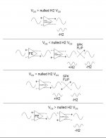
This H2 phase stuff confused the hell out of me 😕
...until I took Papa's text and created this reference diagram.
Front end (FE), I use a transfomer to reverse polarity. (The VFET FE does this, 2nd example IS the P-ch Sony VFET part 1).
Outputs on power amps, I reverse speaker polarity.
It gets more complex when you have more than one H2 dominant amp in your system.
I'm showing only one H2 amp in each example. FE is assumed to be fairly neutral/low THD.
Attachments
Last edited:
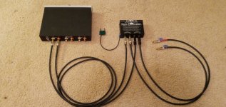
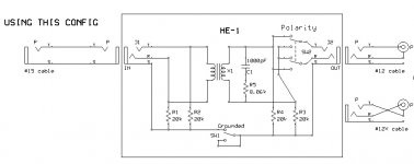
Here's what I use. Isolation transformer with custom cable to reverse polarity.I would love to see a couple of pictures of your B1K with the transformers Cinco 🙄
Later I modified the iso box with a polarity switch so standard cable could be used.
I've been using my B1K lately with MoFo as in 2nd H2 Phase example.
(FE being the B1K, both have +H2 then -H2 after speaker flip.)
I use the HE-1 between source and Iron Pumpkin to reverse polarity into Zen v8.
It has -H2, so 4th H2 Phase example connections to maintain its -H2.
Attachments

Last edited:
Hi, I have put the NuTube and 24V psu on dampening tape inside Purifi power amp. Is it important to connect 24V psu and/or NuTube to ground?
I have to add that I have connected the Purifi amp to mains with power cable without ground because otherwise its humming. Without connection to mains ground its really noiseless.
So the question really is if its sensible to connect 24V psu to the casing.
The Purifi module and Purifi psu both have clean connections to the casing.
So the question really is if its sensible to connect 24V psu to the casing.
The Purifi module and Purifi psu both have clean connections to the casing.
Hi, I made this pre amp a few months back and absolutely love it. It had been working fine for me up until 2 days ago when I noticed a faint hum.
the hum gets louder with volume and even louder when I touch the chassis, especially the volume knob or face plate.
Does someone with more knowledge than me know what the issue may be
the hum gets louder with volume and even louder when I touch the chassis, especially the volume knob or face plate.
Does someone with more knowledge than me know what the issue may be
Attachments
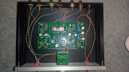
Nutube build into purifi amp. Tube pots on outside of the amp. Fixed input volume with 15k and 35kOhm resistors. Sounds great. No noises at all. 

On Semi Jfets
Hi all,
months ago I shorted something on the left channel while measuring.
Then I bought 40 On Semi j113s. Today I desoldered the output buffers to replace them. I matched the fets. Got pairs and a quad with 12V and a 100 Ohms resistor. Now I read that Q2 is matched to Q1 with R1 for 10% less current.
Can I use the On Semi and how do I find the correct value for R1?
Thanks in advance.
Matthias
Zenmod, thanks, does that mean I can take my quad and then I choose the resistance which gives the 10% difference?
- Home
- Amplifiers
- Pass Labs
- B1 with Korg Triode