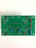
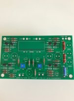
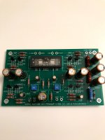
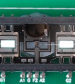
I'm finding the autotransformer solution almost irresistibly interesting for $220.
Watch out for the 14 positions at -3dB steps. That may be too coarse. You may find one position too loud and the next positive too quiet.
Finer adjustment with more positions cost money but in the long run it may be worth it.
Is that the Slagle guy?
Stay away from the $20 switch, that's the horrid one I mentioned.
I haven’t tested all the “cost no object” ones. Goldpoint makes a nice finished volume+selector but price is around $400-600 depending in options. TVC transformers may be the ultimate, not sure who offers DIY versions right now (Slagle is great but no more DIY sales). You can find TVC preamps for sale, at least $800 used if not much more. DACT the true Danish company sells some on Parts Connexion that are nice. Khozmo has lots and lots of options, they’re beautiful but I haven’t tried them for sonic test. Tortuga sells neat kits but you have to accept LDR have a little extra capacitance so there is a mild amount of subjective quality on top of accuracy.
Not sure what Pass Labs high end uses, maybe relay to resistor networks controlled by Alps? Maybe chip controlled for remote? Firstwatt is Alps blue (I think suck), but that’s only this product, all amps are not integrated (no volume).
well, I made what I intended

Hi,
I purchased a chasiss, as i have a built board already. Can someone please provide the hole sizes for:
1. The toggle switch holes.
2. The volume knob cut out(what size knob fits the hole).
Thanks Jeffrey
This was the specification, I am finding out if there were any substitutions due to drill bit availability and will respond when known.
- Galaxy 230x170 full aluminum chassis, anodized black with white printing
- Internal dimensions 40x210x170mm
- LED hole ø2mm
- Left switch
- - Hole ø6.5mm
- - 15mm x 15mm square rear recess, 7mm deep
- Right switch
- - Hole ø6.5mm
- - 15mm x 24mm rectangular rear recess (allows for switch and LED), 7mm deep
- Potentiometer hole ø10mm, with ø32mm round recess in the front ø8mm deep
- Rear RCA holes ø10mm
- Rear power switch hole ø11mm
Last edited:
Just received my kit, and I planned to build it this holiday weekend; however, some relatives from Florida are coming in to avoid Hurricane Dorian. Oh well.
This was the specification, I am finding out if there were any substitutions due to drill bit availability and will respond when known.
- Galaxy 230x170 full aluminum chassis, anodized black with white printing
- Internal dimensions 40x210x170mm
- LED hole ø2mm
- Left switch
- - Hole ø6.5mm
- - 15mm x 15mm square rear recess, 7mm deep
- Right switch
- - Hole ø6.5mm
- - 15mm x 24mm rectangular rear recess (allows for switch and LED), 7mm deep
- Potentiometer hole ø10mm, with ø32mm round recess in the front ø8mm deep
- Rear RCA holes ø10mm
- Rear power switch hole ø11mm
Thanks Jason!
So my relatives have decided to stay put in Florida. I took a general inventory of the Completion Kit parts, and I didn’t see anything for mounting/damping like foam or rubber tape to mount under the Korg Triode IC. What is the general consensus for the best damping material?
Last edited:
...and I didn’t see anything for mounting/damping like foam or rubber tape to mount under the Korg Triode IC. What is the general consensus for the best damping material?
Mine came with some small white foam pads in the box—I took these to be for that purpose?. What a beautiful object!
I'm hoping I can participate in this pre-build... Still waiting for the PCBs to come back in stock. I'm hopeful though!
Mine came with some small white foam pads in the box—I took these to be for that purpose?. What a beautiful object!
I'm hoping I can participate in this pre-build... Still waiting for the PCBs to come back in stock. I'm hopeful though!
I have now built (2) B1 Korgs, (1) NuHybrid headphone amp, (1) NuTube Buffer and (1) NuClassD power amplifier (uses 2 NuTubes, one per channel). That's a total of (6) NuTubes. They have all been mounted using the little double sided foam pads supplied with the device, stuck directly to the PCB and the device leads soldered directly into the PCB.
I only had a problem with one of the NuTubes, and that was one channel of the NuClassD amp. It turns out the filament will resonate around 5 KHz which is the ringing you can sometimes hear when you tap on the tube. Apparently some tubes ring worse than others. Interestingly enough, slightly increasing the NFB using the circuit trim pot designed for that purpose, which reduced the overall tube circuit gain and cleaned up the signal a bit, solved the problem without resorting to additional physical vibration isolation. This problem and its attendant solution may be peculiar to the NuClassD design, which uses both halves of the tube in parallel to provide the voltage gain for one amplifier channel.
The NuTube does not generate enough heat to matter, so one way to reduce any low level ringing that might not be obvious but still might be very subtly coloring the sound, would be to apply some damping to the exposed side of the tube glass and the connections to the PCB. I intend to experiment with this, and will report back.
Mine came with some small white foam pads in the box—I took these to be for that purpose?. What a beautiful object!
I'm hoping I can participate in this pre-build... Still waiting for the PCBs to come back in stock. I'm hopeful though!
I bought the Korg NuTube and Pass DIY PCB a few months ago and I never opened the NuTube box until I read your post. Just as you described, I found two pieces of the white foam pads. I will use these for starters. Thanks. Thanks
People who buy the Pioneer completion kit - I printed out the wrong schematic and stuffed it into the kit bag. The one in the article on firstwatt.com is correct, and also the parts in the kit match the printing on the PCB.
Use the schematic on page two of this article - http://www.firstwatt.com/pdf/art_diy_nutube_preamp.pdf
Use the schematic on page two of this article - http://www.firstwatt.com/pdf/art_diy_nutube_preamp.pdf
Should I assume the lone diode packaged with the LED, resistor and PCB for the Alps Blue Velvet volume pot is the 9.1V diode on the power supply filter (T4)?
I answered my own question--the diode is the 1N4739 Zener diode that goes into the power supply filter.
I measured all the resistors that came in the bag and followed the construction instructions in Nelson Pass' First Watt article: http://www.firstwatt.com/pdf/art_diy_nutube_preamp.pdf.
Starting with the shortest components, I first installed the resistors:

Next, I added the Fairchild JFETs that came with the bias resistors and PCB:

I then added the Nichicon FW capacitors, NuTube and diode:

I will begin work on the chassis and connections tomorrow.
I measured all the resistors that came in the bag and followed the construction instructions in Nelson Pass' First Watt article: http://www.firstwatt.com/pdf/art_diy_nutube_preamp.pdf.
Starting with the shortest components, I first installed the resistors:

Next, I added the Fairchild JFETs that came with the bias resistors and PCB:

I then added the Nichicon FW capacitors, NuTube and diode:

I will begin work on the chassis and connections tomorrow.
small details
For those of us finishing without the completion kit...
Any part #s for the switches and knob ?
Approximate resistor values for LED ?
Grounding scheme same as image with Korg Nutube B1 chassis ?
Thanks
For those of us finishing without the completion kit...
Any part #s for the switches and knob ?
Approximate resistor values for LED ?
Grounding scheme same as image with Korg Nutube B1 chassis ?
Thanks
My son is loving the Korg preamp, but he tells me there is a faint high pitch noise like a moquito. Has anyone encountered this issue and would anyone know what might be causing it?
David
PS: I think it worries me more than him 🙂
David
PS: I think it worries me more than him 🙂
- Home
- Amplifiers
- Pass Labs
- B1 with Korg Triode
