keep it simple - for mono, short wipers of volume pot between channels
This.

Ok, talking about the J113 buffers
The ones I bought were Q1 7.6mA, Q2 34mA and R1 is 221 Ohm.
In a test circuit they draw 2mA.
I thought that Q2 current was meant to be set to the idss of Q1.
In the same test circuit I use two matched j113 at 18mA and R1 as zero ohms.
This uses 9.3mA, and with R1 at 100 ohms it draws 5mA for example.
Can I just use matched J113 jfets of any Idss?
What is your test circuit?
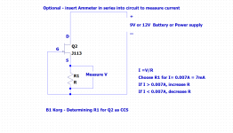
Q1 is the input buffer and Q2 in conjunction with R1 is a Constant Current Source (CCS) that sets the current through Q1.
The current sets the operating point of Q1, and NP prefers 7 to 10 mA:
B1 with Korg Triode
Idss of J113 varies greatly from sample to sample, and is generally much higher than 7mA, although some may be in that neighbourhood. So to use the J113, it is easiest to test and find the value of R1 that will work with Q2 for a current of 7 mA. For this any J113 with an Idss of 7mA or greater will work for Q1 and Q2. R1 is chosen individually for Q2. Matched JFETs are not necessary. The only matching is R1 to Q2 for each channel. If you prefer identical R1 in both channels, then Q2 needs to be matched.
Matching procedure:
Attachments
Hi,
Matching j113 FETs won't be a problem, I bought a 1000 pack,
They all however sit between 15 and 24mA idss.
I have multiple boards I've made to test the proper Idss values as needed.
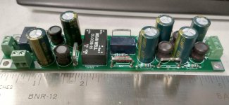
This test board is the B1 buffer circuit I've assembled onto this PCB board.
And I'm feeding it 24v reg power, and watching mA draw.
These jfets in the board are two matched at approx 18mA each, with R1 as 0 ohms.
They read 9.3mA approx, I can easily trim it down via R1 to the correct mA draw if this is acceptable.
Or pick lower idss jfets if I can find them.
I was wondering if I'm on the correct path.
I'm designing my own boards and will also make a DM160 triode tube variation also, as well as the Nutube type.
Thank you for your help

Matching j113 FETs won't be a problem, I bought a 1000 pack,
They all however sit between 15 and 24mA idss.
I have multiple boards I've made to test the proper Idss values as needed.
This test board is the B1 buffer circuit I've assembled onto this PCB board.
And I'm feeding it 24v reg power, and watching mA draw.
These jfets in the board are two matched at approx 18mA each, with R1 as 0 ohms.
They read 9.3mA approx, I can easily trim it down via R1 to the correct mA draw if this is acceptable.
Or pick lower idss jfets if I can find them.
I was wondering if I'm on the correct path.
I'm designing my own boards and will also make a DM160 triode tube variation also, as well as the Nutube type.
Thank you for your help
What is your test circuit?
Q1 is the input buffer and Q2 in conjunction with R1 is a Constant Current Source (CCS) that sets the current through Q1.
The current sets the operating point of Q1, and NP prefers 7 to 10 mA:
B1 with Korg Triode
Idss of J113 varies greatly from sample to sample, and is generally much higher than 7mA, although some may be in that neighbourhood. So to use the J113, it is easiest to test and find the value of R1 that will work with Q2 for a current of 7 mA. For this any J113 with an Idss of 7mA or greater will work for Q1 and Q2. R1 is chosen individually for Q2. Matched JFETs are not necessary. The only matching is R1 to Q2 for each channel. If you prefer identical R1 in both channels, then Q2 needs to be matched.
Matching procedure:
I use a Tkd pot on front to adjust the current. You can get the sound you want. But now I am selling my Korg to a friend. Haven't used it much. There is a Aleph 1.7 as buffer after the korg. There is better possibilities out there.
Hi,
.....................
This test board is the B1 buffer circuit I've assembled onto this PCB board.
And I'm feeding it 24v reg power, and watching mA draw.
These jfets in the board are two matched at approx 18mA each, with R1 as 0 ohms.
They read 9.3mA approx, I can easily trim it down via R1 to the correct mA draw if this is acceptable.
Or pick lower idss jfets if I can find them.
I was wondering if I'm on the correct path.
.....................
View attachment 993964View attachment 993965
It's hard to tell from the pictures what your test circuit is. A schematic would be informative.
If the Idss of both J113 is 18mA, then the current in the J113 CCS/J113 Buffer circuit should also be 18ma if R1 is 0 Ohm.
Current Feedback Headphone Amplifier with Pass B1 Korg Front End
For those that might be interested, I just posted a thread detailing my addition of a headphone amplifier/preamp output buffer integrated with the B1K as the front end.
Current Feedback Headphone Amplifier with Pass B1 Korg Front End
For those that might be interested, I just posted a thread detailing my addition of a headphone amplifier/preamp output buffer integrated with the B1K as the front end.
Current Feedback Headphone Amplifier with Pass B1 Korg Front End
I had my first failure in one of my B1 Korgs. The front panel LED died. First time in my experience that an LED has died. Replacement working fine, but just odd to be listening to music and not seeing the light. Goes to show that any part can fail.
Just ordered my kit - looking forward to the build. It should pair well with either my ACA mono blocks or my Zen.
I see previous posts suggesting placing an eraser on top of the NuTube.
I was wondering whether anyone had tried using the foam block that's attached to the top of the box the NuTube ships in.
I was wondering whether anyone had tried using the foam block that's attached to the top of the box the NuTube ships in.
I was wondering whether anyone had tried using the foam block that's attached to the top of the box the NuTube ships in.
I used the foam block between the NuTube and PCB and it worked well. I was a little concerned about heat, but it doesn't seem to get very hot and so far so good.
Need you wisdom, guys…
For several reasons too long to explain in details (key words are integration of the B1K in a special device, can’t inverse LS cables, will run a HP directly) I will have to invert polarity at source level to get the correct polarity at LS level (while running at 13V bias). That means inverting polarity at B1K input. It turned out I am quite sensitive to absolute polarity, whereas I thought I would only really be to negative H2 LOL
Some sources (MM, my old DAC) don’t enable that polarity inversion, hence thinking about an additional device allowing it. YES, I know, I like it simple and hate extra stages, hence looking into the most transparent and simplest option. Having said that, B1K already added 3 stages vs my passive pre set up, so what is one more stage, ahem… as long as it sounds better?
To do so I picked up 2 easy ways (want to avoid PS complications):
- Transformers, but that didn’t materialised in my head as impedances wouldn’t work properly around the pot / inputs or lead to silly gain reduction, or if at the output wouldn’t cope with my long cables to the amps (unless I am mistaken ???)
- Op amp with unitary gain for best sound, thinking OPA1656 as that one should still be low noise with these impedances and sounds very neutral while musical. Also small form factor = easy to add inside. Kind of additional inverting buffer. That’s seems now the most logical choice to me (glad to be proved wrong though…)
So as it stands the most straight forward seems to be to run an inverter stage around OPA1656 and have it fed by the non symmetrical +24V provided by « SMPS+ Mark’s filter ». Current headroom seems OK for the existing PS if I am not mistaken, convenient as I don’t want to pack an extra PS.
Of course I would like to minimise the impact of this set up, be it on the musical signal path… or on the B1K (being polluted at PS level). Hence a few questions:
1) That inverter stage could be either positioned before B1K entry, so act as a conventional « source out inverter »… but I thought I might be better off putting that inverter stage between the volume pot and the input coupling cap of the B1K. Is also convenient for me as I have a source with 10V output that gets attenuated after the pot, but well… What do you think ?
2) PS for the OPA could be anywhere really if it is positioned after the pot (it will have enough headroom signal level / PS voltage). In a perfect world I would be inclined to benefit from the extra RCs filtering on the B1K board, eventhough the PS rejection of OPA is quite high. On the other hand, I REALLY don’t want to pollute the B1K feed by pluging in an OPA feed where it might hurt the B1K. Any idea where to take the 24V from ? I see teh following possibilities:
a) At SMPS feed level, so upstream / in parallel to B1K feed / similar to T1, hence not benefitting from any B1K filtering… but then I could either "leave it that way" or still create my own extra RC filtering just for the OPA feed, on the OPA board for example, should that be worthwhile
b) From the B1K board directly, at T2, benefitting from some filtering
c) From the B1K board directly, at T3, max filtering but then what about the impact on the B1K, that I defo don't want to disturb
Your POV ?
Will all this make sense ? No clue, I am just willing to try it out. At the end it will be « correct polarity with additional OPA stage in signal path » vs « direct signal with wrong polarity ». The best sounding option to my ears will win, regardless the other intellectual aspects 🙂
Many thanks in advance for your very kind help
Claude

I found I could hear B1K polarity on loudspeakers but did A-B switched reversal test on headphones and could not hear a difference. Maybe because left and right channel audio waves are physically isolated and never combine in the air like with loudspeakers?
I tried some reasonably high quality Jensen line level transformers on the B1K inputs. They did the job but careful A-B listening revealed a very slight "softening" of overall detail and a bit of loss of very low bass extension. I am able to reverse my loudspeaker leads and found no difference in some of the headphones I own that cannot have their leads reversed, so things worked out for me. Inverting opamp may be your best bet.
I tried some reasonably high quality Jensen line level transformers on the B1K inputs. They did the job but careful A-B listening revealed a very slight "softening" of overall detail and a bit of loss of very low bass extension. I am able to reverse my loudspeaker leads and found no difference in some of the headphones I own that cannot have their leads reversed, so things worked out for me. Inverting opamp may be your best bet.
Yep... Jim sadly I am not agile enough to hear music upside down for more than a few minutes GLOL
I will listen to LS aswell, not just HP... the B1K will be integrated in a kind of "swiss knife switch box pre amp" that will enable me to listen / test / connect various pre amps at the same time in one go and also various volume controls, while enabling of course several sources as inputs... and all be quite with few passive quality parts as I want no loss and all is for my main system
To really make use of all that I just need activating switches... I know I will be too leasy to swap cables all the time in my listening room when in the modd for tubes with my main speakers and their bi wiring etc. Of course I could also easily listen to the B1K ALL the time, but them my switch box would lose its purpose and my will to pursue this hobby with more gears to build at DIYA wouldn't be satisfied LOL
Hence having all phase adjusted IN / OUT to enable apple with apple comparisons and listening preferences (read preamp choice) depending on mood and sources.... and wear (no need to use the B1K when my young sun wants to watch an anime)
WHY all that? Because of JIM aka 6L6!! Some years ago HE got me started with that hobby again after nearly a 2 decade brake and why I just wanted to end up with one beloved preamp, one dac, one amp... I am now eager to try several of these, on several HIFI systems in several rooms indeed, but also on the same place in my main room, mainly Pass DIYA stuff... and as I hate to make choices I want to keep them all ready to go and swap from one to another piece of gear with just a switch
All 6L6 fault 🙂))
More seriously, so AOP the best option? Any thoughts on the above?
Cheers guys
Claude
Hi need some help here.
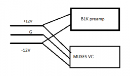
I'm going to add cademyaudio MUSES remote volume control with my B1 Korg, on their web site there is a pdf file shows how to use it with B1 Korg, but seems little complicated, so just make things simpler, I will use a PS with +12V/0/-12V, connect +12v/-12V to B1 Korg, and +12V/0/-12V to MUSES, will it cause any problem? Thanks
I'm going to add cademyaudio MUSES remote volume control with my B1 Korg, on their web site there is a pdf file shows how to use it with B1 Korg, but seems little complicated, so just make things simpler, I will use a PS with +12V/0/-12V, connect +12v/-12V to B1 Korg, and +12V/0/-12V to MUSES, will it cause any problem? Thanks
Hi need some help here.
I'm going to add cademyaudio MUSES remote volume control with my B1 Korg, on their web site there is a pdf file shows how to use it with B1 Korg, but seems little complicated, so just make things simpler, I will use a PS with +12V/0/-12V, connect +12v/-12V to B1 Korg, and +12V/0/-12V to MUSES, will it cause any problem? Thanks
Not sure what you mean by connecting +/- 12V to the Korg. The B1K requires 24V with the 24V ground tied to the common of the +/-15V for the volume control.
On the AA website there is a paper that suggests making quite a number of changes to the B1K pcb in order to make it play well with the AA power supply which powers their volume control. I think this is what you are talking about. Yeah, too much modification of the Korg pcb for my taste.
My preferred alternative is to simply generate the +/-15V (or +/-12V) for the volume control from the 24V B1K supply.
When I first built my B1K I used a basic Mean Well dc-dc converter to make +/-15V in-chassis from the 24V wall wart to drive the Academy Audio volume control while simultaneously adding Mark Johnson's hash filter to the 24V B1K supply. It worked fine. I have now designed a board that includes Mark's filter on all three voltages. It fits down the side of the chassis starting at the power input jack.
Attachments
WHY all that? Because of JIM aka 6L6!! Some years ago HE got me started with that hobby again after nearly a 2 decade brake and why I just wanted to end up with one beloved preamp, one dac, one amp... I am now eager to try several of these, on several HIFI systems in several rooms
…
All 6L6 fault 🙂))
I hear that a lot!
😀 😀 😀
That's what I thought about, but you mentioned the ground of B1K need to connect to common of MUSES PS, so it won't workNot sure what you mean by connecting +/- 12V to the Korg. The B1K requires 24V with the 24V ground tied to the common of the +/-15V for the volume control.
On the AA website there is a paper that suggests making quite a number of changes to the B1K pcb in order to make it play well with the AA power supply which powers their volume control. I think this is what you are talking about. Yeah, too much modification of the Korg pcb for my taste.
My preferred alternative is to simply generate the +/-15V (or +/-12V) for the volume control from the 24V B1K supply.
When I first built my B1K I used a basic Mean Well dc-dc converter to make +/-15V in-chassis from the 24V wall wart to drive the Academy Audio volume control while simultaneously adding Mark Johnson's hash filter to the 24V B1K supply. It worked fine. I have now designed a board that includes Mark's filter on all three voltages. It fits down the side of the chassis starting at the power input jack.
If I add separate PS for MUSES only, does two ground need to be connected?
Thanks
this one DC-DC Buck Step-down Volt Converter Dual Output +-5V +-9V +-12V +-15V Power Supply | eBay may work
Attachments
Last edited:
- Home
- Amplifiers
- Pass Labs
- B1 with Korg Triode