I was looking at the Academy Audios volume control board as well and thought this would be a great place to use a second wallwart and Wapo’s single line to bipolar board.
Wouldn’t this be easier with a dedicated bipolar supply for the volume control? Or maybe just a bipolar supply with the positive side feeding the b1? I’ve read Academy Audio’s application notes…seems needlessly complex into me.
An all-linear supply would have its own complications and would take more space.
I think perhaps you have not personally experienced a diyaudio store B1K chassis? It's spacious for the B1K board but as soon as you start adding things, suddenly it's not. My chassis will hold the B1K, the triple power supply with filters, and a third board to hold relay input and output controls with delay, a Mute circuit, and a 12v trigger. Space is at a premium and the shape of the boards is not flexible, they have to fit around the B1K board. That's why this board is only 1.15 inches wide.
If you try to include an entire linear PS in the chassis there is no way. If you put the transformer outside the case that's additional complication, a new and bigger power connector and added heat in the chassis and not at all my preference because I like small and elegant and functional. I choose to use the single voltage 24V smps wall wart per Nelson's design, and that choice drives this solution.
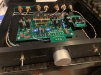
Another B1 Korg is born! I put a smps filter in, and used a Pete Millet vibration mounting kit in the build. This one doesn’t have the microphonics problem I was worried about. I don’t know if it’s the tube itself, the mounting kit, or both.
I used my Akitika signal generator, Focusrite scarlett solo, and REW software to measure distortion profiles at 1kHz and 1V. I found the null point and ran up and down to 1.5% positive and negative phase for both channels, then set it for 1.3% negative.
Once again the DiYAudio build guide is FANTASTIC. This is a fun project build and sounds quite nice!
Attachments
Hi everyone, hoping someone has come across and worked this one out.
I'd like to know how to make my own J113 transistor sets or Q1 and Q2 and how to select the correct R1 value.
What idss is needed and how do I calculate it, and how does that effect R1 and the best way to calculate that also.
I have a bought set of j113 with a korg Nutube.
But I plan to experiment with some DM160 tubes also and would like to be able to make my own buffer sets. And not just copy the values I have in my set already if possible.
I'd like to understand this more.
Thanks in advance
Another B1 Korg is born! I put a smps filter in, and used a Pete Millet vibration mounting kit in the build. This one doesn’t have the microphonics problem I was worried about. I don’t know if it’s the tube itself, the mounting kit, or both.
I used my Akitika signal generator, Focusrite scarlett solo, and REW software to measure distortion profiles at 1kHz and 1V. I found the null point and ran up and down to 1.5% positive and negative phase for both channels, then set it for 1.3% negative.
Once again the DiYAudio build guide is FANTASTIC. This is a fun project build and sounds quite nice!
ROTLOL... now we got to get those test points to the back panel, with a switch selector in the front and an old fashioned bakelite calibrated VU meter.
😀
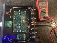
Updated version…. Changed to 25 turn pots and added some test point jacks to the back of unit for ease of adjusting. It’s singing now with a rebuilt F5 clone I also finished this week.
YOU DID PUT THE TEST POINTS...
Awesome..... AWESOME.

Might have to pack that Korg Nutube so UPS won't wreck it....
How do you think it'll compare with my Conrad Johnson PV9 with the full boat Teflon cap upgrade?

I noticed by your list... you don't have a B1 in a blonde, burl wood humidor.
I do.
It's great for late night music... it adds that.... smoky sound to Sinatra.
IDEA for Christmas Bumper Sticker:
My amp has bigger heatsinks than yours.
I do.
It's great for late night music... it adds that.... smoky sound to Sinatra.
IDEA for Christmas Bumper Sticker:
My amp has bigger heatsinks than yours.
Last edited:
I can’t see clearly from the picture but it looks like T7&T8 connect to the same binding post. Is it OK to have them connected together like that?
I’m just asking….😉
I’m just asking….😉
Updated version…. Changed to 25 turn pots and added some test point jacks to the back of unit for ease of adjusting. It’s singing now with a rebuilt F5 clone I also finished this week.
Thanks for the clarification…I just couldn't make out if there was another post below the (black) ground post..
Last edited:
Zoom int the photo, there’s two posts.
So a jumper between the two posts would turn this into a MONO preamp?
Hmm... it needs a STEREO, MONO switch then.
With two lights to indicate status.
Looking at the schematics... T7 (and T8) are between Q1 and Q2... right before an output cap and the resistor bridge to the output. So this is the signal output before the AC coupling.
If I were to short T7 and T8 I would be combining both L and R channels. I imagine there might be effects on Left and Right Q1/Q2 but since we're summing the signal....
Perhaps the connection should be made after the cap, between the 100 and 33.2K ohm resistors?
If I were to short T7 and T8 I would be combining both L and R channels. I imagine there might be effects on Left and Right Q1/Q2 but since we're summing the signal....
Perhaps the connection should be made after the cap, between the 100 and 33.2K ohm resistors?
Last edited:
mono - either in front of line stage itself, or on output
(never connect DC carrying points, recipe for trouble)
though, simple summation of L and R channels is just crude mono
proper mono is whole different animal
(never connect DC carrying points, recipe for trouble)
though, simple summation of L and R channels is just crude mono
proper mono is whole different animal
I know, I know.....
So the 'mono' switch should be a short between the 332K resistor ladder at the input of Q1 ( the other Q1... I don't know they published schematics reuse the names...).
That would keep the input source from seeing the short (behind a cap and a 1K resistor).
I think I'll keep it pristine...
So the 'mono' switch should be a short between the 332K resistor ladder at the input of Q1 ( the other Q1... I don't know they published schematics reuse the names...).
That would keep the input source from seeing the short (behind a cap and a 1K resistor).
I think I'll keep it pristine...
Last edited:
I only stream music. The streaming device I use I can go into the audio-settings and set it to "mono" or "left" or "right" and then of course stereo. The "left" setting puts left channel in both channels etc. It can be useful during testing. Then I don't need any mono switch at preamp level.
- Home
- Amplifiers
- Pass Labs
- B1 with Korg Triode