@ Chanting
If the failure source is not eliminated
and you replace the damaged component only
then the same situation does reproduce again.
Lesson learned.
If the failure source is not eliminated
and you replace the damaged component only
then the same situation does reproduce again.
Lesson learned.
So....
My nuTube has failed again, pretty much exactly as previously described (https://www.diyaudio.com/forums/pass-labs/313612-b1-korg-triode-635.html#post6598822).
Same channel. Was careful to measure and set the voltage at the test point to 9v.
Suggestions for troubleshooting? It would be nice to be able to do some informative probing without having to replace the nuTube.
Or should I go ahead and build the Wayne's BA2018 linestage (or the Elekit tube preamp)? Attraction of the Elekit is it would eliminate the need for an outboard phono preamp.
-- Thing
Please measure voltages from T1 - T8 to ground and post results and compare to what Nelson says:
Initial Power Up:
Put the adjustment pots at the center position.
Connect the 24V supply
Look at the Nutube - the Cathodes should lite up as blue in about 3 seconds or so. If they are
orange or red, unplug the power supply immediately - there is too much bias current.
With a voltmeter referenced to Ground (all 4 mounting holes are at ground) measure:
T1 = 24V approximate
T3 = 23V approximate
T4 = 9V
If these values are good within .5V you should be OK. If not, carefully check your circuit for
errors.
T5 and T6 should be at about 0.6 VDC This is the bias to the Cathode heaters.
T7 and T8 are adjusted by the on board pots for each channel. They should be set to 10 volts
and allowed to sit for a bit, while the tube warms up.
After a few minutes and no smoke, we adjust the T7 and T8 voltages as follows:
Voltage at 12 VDC is approximately the 2nd harmonic null point where we get about .3 %
distortion in 3rd harmonics. As we go lower we start getting positive phase 2nd harmonic, and it
will hit 1.5% at 1 volt AC output with about 9.5 VDC on the T7 or T8 test points. Voltages
higher will give negative phase second harmonic.
This is a reasonable calibration - 0.1V either way changes the distortion by about 0.1%
Clockwise on the pot from the null spot makes for less Plate voltage, and positive phase
second harmonic, counterclockwise makes for more negative phase second harmonic.
If you have a distortion analyzer which gives you the percentage but not the phase, then just
start out with the Plate voltage high (CCW pot) and turn it clockwise to the point where it is
minimum, and then go further for + phase, or back up for - phase.
The reference setting for this project, are 9.5V on T7 and T8, which gives a positive phase at
about 1.5% at 1 volt output. You are free to set it elsewhere.
@elwood625 - Thanks very much for the detailed troubleshooting information.
Fairly certain I checked all those voltages when the nuTube was replaced, but it is possible I missed one. The cathodes most definitely only burned blue/green and there was no visible difference in brightness or color between the two.
FWIW, reactions here on the original failure were primarily comments on how nuTubes are not the most reliable device and that a mechanical shock could be to blame.
Will share what I discover. Again, I appreciate the help.
-- Thing
I am not EE Savvy and am making an inquiry to help with the design for a Balanced KB1 I am to have produced for myself.
The need to make the inquiry is a result of the EE who has designed and Built my 845 Monoblocks, taking the Amp's back to convert them to a Balanced Design, hence the KB1 Balanced Design to be produced by a friend for myself.
The EE has made it known the KB1 has a Output Gain that will be quite high for the Amp's he is to work on and has suggested this is lowered on my Balanced KB1Build.
He has looked at the KB1 and claimed there is 16db Gain.
Has there been any KB1's produced that have a reduction to this 16db Gain that has been mentioned ?
As per the usual any information supplied will be greatly appreciated.
Problem is that the circuit's character is also a function of the gain of
the NuTube in that circuit, so to change the gain you will also change
the character. An easy solution is to attenuate the signal at the input.
the NuTube in that circuit, so to change the gain you will also change
the character. An easy solution is to attenuate the signal at the input.
Papa, this is possibly in the same alley as the discussion about the possible effect of «low» IDSS JFETs in the BA-3 FE. I can not find a clear answer to this question. Ie, could you please consider answering my greenhorn viking question about what - if any - consequence it has using 5-6mA JFET bias vs the prescribed 8mA (with 10mA IDSS devices)?
I built with devices achieving 5.5mA with stock R3/4 values. But I have Toshibas @ 9.99mA to be implemented once I get around to it 🙂

Andy
I built with devices achieving 5.5mA with stock R3/4 values. But I have Toshibas @ 9.99mA to be implemented once I get around to it 🙂
Andy
Last edited:
jfets in kgb1 are "just" buffers, so their Idss is not influencing funny toob work, nor anything else
I am sorry if the question was unclear, it prolly was, but I am wondering about the BA-3 FE. How does a couple of mA less JFET bias affect the rest of the FE circuit - if at all?
I can move the question to the BA-3 thread 🙂 been wondering about this for some time.
Regards,
Andy
I can move the question to the BA-3 thread 🙂 been wondering about this for some time.
Regards,
Andy
For starters, you can run the lower Idss at higher currents:
Beyond the J Fringe
Also, as ZM points out, you can run buffers self-biased at lower Idss with little issue.

Beyond the J Fringe
Also, as ZM points out, you can run buffers self-biased at lower Idss with little issue.
Thank You Nelson
My Temporary idea chosen, is to use already owned fixed value 'reduced db' Rothwell Attenuators.
Hopefully these should be a fix for the short term.
The EE who is to be working on the Monoblock Power Amps has suggested a method to have a variable attenuation at the KB1 Output, which will allow myself to choose a level of Gain.
I really want to keep with the KB1, the loaned model used in my system is quite special, even with my new found knowledge about the Gain, and how this might be responsible for an increased level of noise, when used in the system as is.
This information supplied is lending itself to keeping that ambition for the KB1 ongoing, which is a very satisfying outcome.
My next session will be with a Rothwell Attenuator in use.
For starters, you can run the lower Idss at higher currents:
Beyond the J Fringe
Also, as ZM points out, you can run buffers self-biased at lower Idss with little issue.
Thank you so much, Mr. Pass, and ZM too!
I have read that article, but - as always - realize I have ways to go wrt understanding both the article, but more importantly the individual parts of circuits. Thanks for helping me along! Seems for now and until 2050 or so following recipe is the way to go

Seems my impression that bias is equally important in «all» parts of a circuit is not correct.
Now, reading and rereading is long overdue 🙂

Last edited:
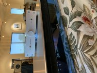
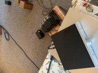
Another Korg Nutube B1 is alive
My friend goaded me into a race to build our Korg B1’s.
He has not started and I completed it last night.
Just hooked it up to test an old pair of speakers. Sony CD to Korg to Carver Crimson 275 to Realistic Minimus 7.
Speakers on the floor and there is a soundstage!
Thanks 🙏🏽
My friend goaded me into a race to build our Korg B1’s.
He has not started and I completed it last night.
Just hooked it up to test an old pair of speakers. Sony CD to Korg to Carver Crimson 275 to Realistic Minimus 7.
Speakers on the floor and there is a soundstage!
Thanks 🙏🏽
Attachments
Last edited:
Left channel is dead
I have played on the B1 for a few months without any problem but now the left channel is out. The left triod is black, voltage on T7 is 20V and not adjustble with the trimpot. The trimpot have been tested and is fully working.
Thankful for any ideas about the cause.
I have played on the B1 for a few months without any problem but now the left channel is out. The left triod is black, voltage on T7 is 20V and not adjustble with the trimpot. The trimpot have been tested and is fully working.
Thankful for any ideas about the cause.
- Home
- Amplifiers
- Pass Labs
- B1 with Korg Triode