Experts, please... Am I correct to assume that I can fire up the circuit without the tube for a test purpose?
So I removed the tube and the hum is gone. Can you make something useful out of it? Bad tube maybe?
🙁 This build has been most frustrating experience I've ever had. Seems like I've examined everything...
Well, let's see if this image will last. Sorry, I am NOT tech at all. I am a builder.
OLYMPUS-DIGITAL-CAMERA — ImgBB
OLYMPUS-DIGITAL-CAMERA — ImgBB
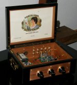
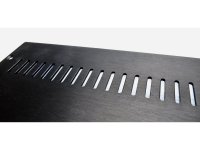
It is a balancing act when you work with a completed enclosure. You get the benefits of the design and manufacture, but now your every stroke of blade is a chance at failure. Now, so as this may be true, imagination can be held as a tool to reconstruct the failure. Case in point here is right on the front panel. Short story, I miss drilled the right most hole for the selector knob, making me enlarge it to be at the right height to the other knobs. This is when the idea of using the brass disc's came into play. It stepped up the stage of building one notch. I could no longer use knobs that were generic, but had to accompany the richness and solidity that the brass disc's gave. The frustration had turned into reward.
Ixnay, beautiful build.
External links to photos often disappear after awhile, so the best practice is to upload it directly:
Here's what Mark did:
He downloaded your beautiful photo to his computer.
From the "Reply to Thread" interface:
>He clicked on "Go Advanced" button
>Scrolled down to "Manage Attachments", and clicked on it.
...a pop-up window appeared
>Clicked on "Choose File"
>Selected your file, and clicked on "Open"
>Then he clicked on "Upload"
...it's file name appeared in the "Attach Files" interface area.
>And lastly, he click on "Submit Reply"
...and now it will always be available for people to see. 🙂
Attachments
The frustration had turned into reward.
And creative beautiful preamp
 Congratulations looks amazing
🙁 This build has been most frustrating experience I've ever had. Seems like I've examined everything...
For some bigginers this was the most easy tube preamp build.
Are your the kit from the store or personal choice of the components version ?
Show some pictures, photos both sides can help find solutions 😉
Smps psu kit version are very quiet , low ripple model. What is your psu ?
Hi. Just completed to assembly the B1 kit. Unfortunately, the Reading of the T8 has the min. of 19V that I am not able to get what it should be as at the T7 which has 9.5V. Double checked everything seems no mistake. Any help? Thank you!
Any help please?
Don't you confuse jfets JQ1 with Q2 ?
Not easy to see without your circuit pictures..
I don’t think the Q1 and Q2 have been mixed up as I was soldered all the Q1 till I before I even open the bag of Q2.
Will take photos later tonight
Thank you
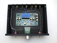
Nothing new under the sun. Just another kit completed (few weeks back)!
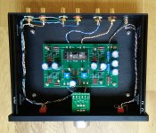
For once was nice just soldering without drilling. 🙂 Well I drilled the bottom plate to bolt larger feet...
From the kit I just swapped the electrolytics with some surplus I had and used a red LED (I know... it is not blue... but neither green as the one in the kit).
Thanks Nelson to sparkle again the DIY restlessness in me (after ~10 years), 6L6 for his build guide and everyone here for publicly sharing their knowledge and experience.
P.S. I do have a question. Why R and L labels are inverted (or it is just in my mind) on the back panel? Not that it is a problem as you clearly see from the picture. 😀
Attachments

For some bigginers this was the most easy tube preamp build.
Are your the kit from the store or personal choice of the components version ?
Show some pictures, photos both sides can help find solutions 😉
Smps psu kit version are very quiet , low ripple model. What is your psu ?
Thank you for your reply. This project driving me insane! 🙂
I think I posted some picker above, but I will do it again.
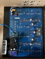
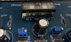
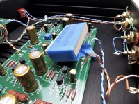
Basically a board I got from forum member:
1. Papa's circuit for the B1k
2. Salas' Ubib regulator for the audio stuff
3. DC-DC converter for 5V filaments (some resisters are changed to account for this)
4. Output delay relay taking unregulated DC and feeding separate 7815 regulator
5. Salas' input selector unpopulated in my case
All voltages are are spot on, input is grounded (of course tried connected to the source and unplugged), tried all sorts or chassis grounding and now just a board with nothing on it, just power. Have very loud hum. As I say before if I remove the tube, it is silent. To avoid amp grounding I was evaluating with my headphones. Also my tube is super microphonic, rings as crazy even if I snap fingers a meter away. I tried all sorts of isolating material mentioned in this post.
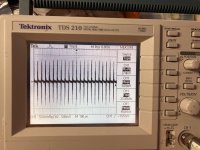
I also attaching some scope measurements at the output. this is my first time with digital scope, so I "zoomed in" on higher frequency component, there are also lower freq envelope around what is shown.
Attachments
are you only one trying that pcb?
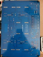
that mesh pour , on top and bottom - is that audio GND?
they are nice, but being of benefit only when experienced designer is on task, knowing to which point in circuit mesh is going to be connected, to serve as shield, instead as emitting antenna
it can be SMPS, it can be something else, but tricky to decipher when you have so many things combined
I would try any external PSU, entirely made by Papa's original schematic ......... incorporating heater PSU for directly heated tube can be helluva fun ....... as you already know
complete schmtc, if you have it, can be handy and probably only way to find what's wrong
PKI, I don’t recognize your PCB. It is not from the DIYaudio store. Where did you obtain? Do you have a schematic?
Thank you for your reply. This project driving me insane! 🙂
Let's try start a step by step cure 😀
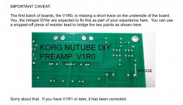
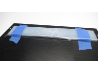
First reflow Korg Nutube pins solder joints from both sides
Second try fight microphonic like on the photos from 6L6 great build guide
B1 with Korg Nutube - diyAudio Guides
Close all air flow holes in your chassis if some.
Imho metal chassis is better for this triode preamplifier.
Report , stay in tune
Attachments
-
 71157117-CCD3-4562-B057-637AABDBBA14.JPG356.1 KB · Views: 185
 -
 39EF7DC5-6539-42C8-B08E-628BF32F8007.JPG479.1 KB · Views: 187
 -
 B450F23E-0C66-4859-AF2B-A8120308F245.JPG228.5 KB · Views: 161
 -
 B6736440-346E-46DE-A1FB-F500180CE3C1.JPG200.8 KB · Views: 120
 -
 ED99A5DF-C876-4710-93DD-889EF3693D1F.JPG180.5 KB · Views: 129
Thank you for your reply. This project driving me insane! 🙂
I think I posted some picker above, but I will do it again.
Basically a board I got from forum member:
1. Papa's circuit for the B1k
2. Salas' Ubib regulator for the audio stuff
3. DC-DC converter for 5V filaments (some resisters are changed to account for this)
4. Output delay relay taking unregulated DC and feeding separate 7815 regulator
5. Salas' input selector unpopulated in my case
All voltages are are spot on, input is grounded (of course tried connected to the source and unplugged), tried all sorts or chassis grounding and now just a board with nothing on it, just power. Have very loud hum. As I say before if I remove the tube, it is silent. To avoid amp grounding I was evaluating with my headphones. Also my tube is super microphonic, rings as crazy even if I snap fingers a meter away. I tried all sorts of isolating material mentioned in this post.
I also attaching some scope measurements at the output. this is my first time with digital scope, so I "zoomed in" on higher frequency component, there are also lower freq envelope around what is shown.
May I suggest that you seek help from the vendor that you purchased your board first? That might be the best approach as the vendor best knows the design of the board and should be able to offer troubleshooting help (assuming that they are legitimate).
are you only one trying that pcb?
that mesh pour , on top and bottom - is that audio GND?
they are nice, but being of benefit only when experienced designer is on task, knowing to which point in circuit mesh is going to be connected, to serve as shield, instead as emitting antenna
it can be SMPS, it can be something else, but tricky to decipher when you have so many things combined
I would try any external PSU, entirely made by Papa's original schematic ......... incorporating heater PSU for directly heated tube can be helluva fun ....... as you already know
complete schmtc, if you have it, can be handy and probably only way to find what's wrong
From what I see it is connected to the GND at the bottom layer. I can not see at the top as I already have parts soldered at the main "GND star" point. Also the trace layout doesn't have the mech.
Swapping all parts back to the store board was my last resort, but I am getting there... 🙂
wengtech (designed the board) and Marra member use it and say that there is no hum, but Marra for example could not stabilize the PSU and uses external UBib instead so it is not completely fair comparison.
I do not have the exact schematics, only PCB layout, but I respect any IP and do not feel comfortable posing it here without permissions.
From what I see things are pretty straightforward, just modules, but apparently I am missing something. Only thing is I am kinda worried is that the delay psu circuit shares same GND audio GND. Should be fringe though.
PKI, I don’t recognize your PCB. It is not from the DIYaudio store. Where did you obtain? Do you have a schematic?
May I suggest that you seek help from the vendor that you purchased your board first? That might be the best approach as the vendor best knows the design of the board and should be able to offer troubleshooting help (assuming that they are legitimate).
I am trying to communicate, but I assume the member is busy and our communications are delayed in time, and after a couple of basic suggestions that checked in his main message now is that everything should work 🙂.
Also I double, triple... checked and re-soldered/reflowed everything at this point and tried all ways of dealing with the microphonic. Microphonic is something can be managed (still a bit to much for my taste)
- Home
- Amplifiers
- Pass Labs
- B1 with Korg Triode