Just listen to music. 🙂 🙂 🙂 It’s significantly more interesting and enjoyable than worrying if the CD is going to run properly all night, or for days...
The only break-in happens between the ears.
The only break-in happens between the ears.
Yeah, I always thought the break-in thing was mostly between the ears too.
Nice blue LED rtate. 😎
Nice blue LED rtate. 😎
Here are some pics of the final build. I went a little overboard on this one so it's a bit of overkill but I'm sure nobody minds that.
Hi Mrshazbot-
Can you tell me more about the process of implementing the remote volume control?
-Wes
The PSU is a Sigma 11 24v regulated supply.
The volume control is a Khozmo remote controlled attenuator
I got the Nutube and carrier board from Pete Millet
The input selector is the Select-2 from Tubecad
I still need to glue the plexiglass inserts on the front panel but haven't gotten there yet but it will be smoked glass on the front.
A couple things I need to work out - My input selector pops. The other thing is that I have an Intel NUC -> DAC -> preamp and I can hear a slight buzz when the CPU is working. It wasn't there before but now I can hear it. I can't hear it while playing music but can when nothing is playing. Probably some sort of grounding thing.
Anyways, it sounds great. I have it hooked up to an F5 and it makes the bass much stronger (didn't expect that) and almost 3 dimensional but has a slight echo in my ears on the low end.
Thank you Mr. Pass !
Kevin
I could use a little help. The 270 ohm 3W watt resistor is hot to touch after 30 seconds. None of the other components are a little warm. After about 30 minutes, the Zener Diode is getting a little warm.
I am listening to the B1K four about 45 minutes, and both channels sound great! Here are the measurements:
T1 = 23.88v
T2 = 23.06v
T3 = 22.24v
T4 = 8.69v (should be closer to 9.1v ?)
T5 = 0.564v (should this be closer to 0.6v, like the other channel T6?)
T6 = 0.602v
T7 = 10.01v (after adjusting the 10k trimmer)
T8 = 10.02v (after adjusting the 10k trimmer)
The PCB is drawing 82.16 mA and is stable. Measured is without the power LED in the circuit.
The voltage across the 270 ohm 3W resistor is 13.57v
I lifted one end of the 270 ohm 3W resistor and measured 268.4 ohms
The current going into the PCB without 270-ohm resister is 31.33 mV
My first thought was one of the capacitors had its polarity reversed, but they all visually check out OK with the black stripe being opposite + sign on the PCB. I had also double checked them before soldering.
I took multiple resistance measurements between the left and the right channel with the power disconnected, and they appear to match. I am just trying to find out in one channel is different than the other.
I ran a 1 kHz sine wave through each channel, and on a pocket digital oscilloscope, the wave looks smooth and symmetric.
I did try to follow the build guide. For Step 43 PSU test, I got about 8.8v (sorry did write it down at the time). I noticed 207ohm 3W resister was warm then, but I thought it was because there was no load on the Zener Diode.
Then I check the BOM versus the parts I received from Digikey, and all of them matched. I also checked the resistors being the correct location vs. Nelson's document. For my 1000uf caps, I am using Nichicon UKA1E102MPD1TD (Digikey 493-4648-1-ND). I read somewhere on DIYAudio.com they were a better grade for audio and had the 5.0mm lead spacing.
FYI, I order my parts from Digikey rather than buying the completion kit. I had many parts (switches, RCA jacks, power supply, ALPs pot, standoff, etc.). I have made mistakes building stuff before, but this is the first time I haven't been able to find my mistake.
I will order a new Zener and 270 ohm 3W resistor and see if I can get closer to 9.1.
Any ideas on what to check?
Thanks, Tom
I could use a little help. The 270 ohm 3W watt resistor is hot to touch after 30 seconds. None of the other components are a little warm. After about 30 minutes, the Zener Diode is getting a little warm.
I am listening to the B1K four about 45 minutes, and both channels sound great! Here are the measurements:
T1 = 23.88v
T2 = 23.06v
T3 = 22.24v
T4 = 8.69v (should be closer to 9.1v ?)
T5 = 0.564v (should this be closer to 0.6v, like the other channel T6?)
T6 = 0.602v
T7 = 10.01v (after adjusting the 10k trimmer)
T8 = 10.02v (after adjusting the 10k trimmer)
I will order a new Zener and 270 ohm 3W resistor..
If you can buy similar size 270R resistor then 5 Watts run cooler.
All voltages with - or + 0.5V tolerance are OK.
Best way to get close the same voltages values is precisely matched, tested the same resistors values on both channels.
🙂Just for perfectionist better sleep.
With use of 1% resistors tolerance you are good anyways without matching.
Edit: From Mr. Pass article the most important is 475R pair
with this two resistors heaters current adjustement is possible.
Have a nice day
Attachments

Experts, please... Am I correct to assume that I can fire up the circuit without the tube for a test purpose?
Started my B1 kit today and have a couple of questions....
Working on steps 38-42 in the build guide, my kit contained 2 ublue resistors and one brown but I checked the resistance and it matched the PCB, so I installed them.
I initially installed the 9.1v diode backwards and applied power, I have since reversed it. Now the PSU tests fine with the exception of the diode, which is reading 0, do I need to replace this now since I had reversed it?
You won't break it...
Got the answer from THE expert himself 🙂 Thank you Nelson!
Balanced Korg NuTube B1 Preamp
Hello everyone. This my first time posting on this forum. I am a beginner diy’er. I have built 3 ACA’s so far two for me and one for a friend. I have also built the Korg NuTube as well. I was curious though if there was a build guide on making the NuTube preamp balanced to take advantage of the ACA xlr inputs. I have really enjoyed doing these builds. Very satisfying to put a bunch of components together and have something that sounds so beautiful! I am running these amps to a pair of Audio Nirvana 10 inch full range speakers with 95db per watt in cabinets that I have built and they sound awesome so far. Any help with a balanced version of this preamp would be greatly appreciated!
John C
Curious about the results: Has anyone tried this with a planar speaker? Seems like it might generally work better since some speaker "n+1 way" designs may have variability in phase/polarity of different drivers.
My view: unless you have a need to accept balanced inputs, it would be easier and more reliable to use a transformer to convert the unbalanced output of the B1 Korg to a balanced output that would feed an XLR male output jack.Hello everyone. This my first time posting on this forum. I am a beginner diy’er. I have built 3 ACA’s so far two for me and one for a friend. I have also built the Korg NuTube as well. I was curious though if there was a build guide on making the NuTube preamp balanced to take advantage of the ACA xlr inputs. I have really enjoyed doing these builds. Very satisfying to put a bunch of components together and have something that sounds so beautiful! I am running these amps to a pair of Audio Nirvana 10 inch full range speakers with 95db per watt in cabinets that I have built and they sound awesome so far. Any help with a balanced version of this preamp would be greatly appreciated!
John C
I believe there were posts within this thread on appropriate line output transformers. Jensen and Cinemag make appropriate transformers. The output of the B1 Korg really starts to get quite a bit of distortion (albeit the type you may want) above 1 volt output or so if I remember the distortion curves correctly. Accordingly, you may want to look for a transformer that is not just a 1:1 output, but has a 1:2 step-up characteristic. Any higher (e.g., 1:4), and you may end up not outputting the level of 2nd harmonic distortion that is desired to have the psychoacoustic effects that Mr. Pass was trying to achieve.
When I was briefly researching this, it appears that the Jensen transformer recommended by a poster was no longer available, so you will have to hunt for something that is appropriate. I would certainly chose a transformer with a partial nickel core for higher fidelity (less capability of the core for saturation and distortion) and quadfilar winding for better high frequency response. One I was considering was the JT-123BMCF with 80% nickel core and quadifilar windings, which has a 1:2 step-up capability.
I think others with better understanding of line output transformers could contribute their thoughts and recommendations.
All Hail Korg!
If I am lucky, I will successfully load a photo of my Korg project. The installation process was challenging since I am using an expensive cigar box that is covered in black leather.
OLYMPUS-DIGITAL-CAMERA — ImgBB
OLYMPUS-DIGITAL-CAMERA — ImgBB
If I am lucky, I will successfully load a photo of my Korg project. The installation process was challenging since I am using an expensive cigar box that is covered in black leather.
OLYMPUS-DIGITAL-CAMERA — ImgBB
OLYMPUS-DIGITAL-CAMERA — ImgBB
Last edited:
If I am lucky, I will successfully load a photo of my Korg project. The installation process was challenging since I am using an expensive cigar box that is covered in black leather.
That is totally awesome!!! I’m inspired.
Hi. Just completed to assembly the B1 kit. Unfortunately, the Reading of the T8 has the min. of 19V that I am not able to get what it should be as at the T7 which has 9.5V. Double checked everything seems no mistake. Any help? Thank you!
My view: unless you have a need to accept balanced inputs, it would be easier and more reliable to use a transformer to convert the unbalanced output of the B1 Korg to a balanced output that would feed an XLR male output jack.
I believe there were posts within this thread on appropriate line output transformers. Jensen and Cinemag make appropriate transformers. The output of the B1 Korg really starts to get quite a bit of distortion (albeit the type you may want) above 1 volt output or so if I remember the distortion curves correctly. Accordingly, you may want to look for a transformer that is not just a 1:1 output, but has a 1:2 step-up characteristic. Any higher (e.g., 1:4), and you may end up not outputting the level of 2nd harmonic distortion that is desired to have the psychoacoustic effects that Mr. Pass was trying to achieve.
When I was briefly researching this, it appears that the Jensen transformer recommended by a poster was no longer available, so you will have to hunt for something that is appropriate. I would certainly chose a transformer with a partial nickel core for higher fidelity (less capability of the core for saturation and distortion) and quadfilar winding for better high frequency response. One I was considering was the JT-123BMCF with 80% nickel core and quadifilar windings, which has a 1:2 step-up capability.
I think others with better understanding of line output transformers could contribute their thoughts and recommendations.
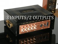
I recently built a little box that has two of the BMCF transformers in it. It accepts two RCA inputs and has two XLR outputs. So it's usable with any pre-amp.
Another option, described here, is to put an impedence matching circuit in front of an XLR jack. This is the circuit described in section 2.4 of that paper. With the B1 Korg, the values would be 33.2K for the one they show as 100k; 100 ohms for the other one; and 10uF for the cap.
I've been thinking about making a little PCB for this, partly just to learn how to do that.
- Home
- Amplifiers
- Pass Labs
- B1 with Korg Triode