Nope.
Only listening tests.
I was satisfied that the maestro who designed this buffer had done his part.
Only listening tests.
I was satisfied that the maestro who designed this buffer had done his part.
Is there a difference in sound, with 18 volts power supply, or 24 volts ?
I powered my B1 with LM317 adjustable regulator.
I tried increasing voltage from 18v to 24v.
What I found was at 18v sound was fantastic and the jfets were cool to touch.
At 20v sound was same but the jfets were warm to the touch.
At 24v the jfets started to be very hot with no audiable difference to the sound.
The lower jfet in the B1 is a current regulator.
Increasing voltage does not increase current but turns the excess into heat
dissipation untill the limiting value reaches and after that thermal runaway causes the jfets to burn.
thanks for sharing your experience ..
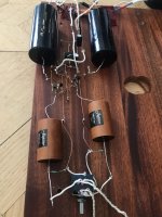
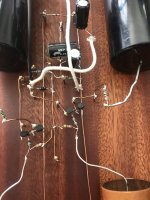
Built my first B1 hardwired, this was just a tryout. I got a B1 on a experimental card from a friend. It sounded so good that I decided to make one myself.
I bought the Jupiter copper foil in wax 1uf and Mundorf Silver Gold in oil 10uf and replaced them on the card.....really nice.
Then I tried to build one hardwired from the original drawing and it worked!
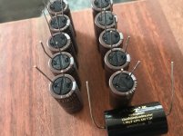
I used a Blue Alps that I had laying in my workshop. Now I’m planning the final version, with 10X1000uf SILMIC II, z-foil resistors for r102/104-r202/204 and the rest will be a mix of Holco and AMRG.
Next step will be a stepped attenuator, I’ve had a Khozmo in a previous project and it was really nice, but I’m considering going with Seiden this time. Will it be worth the extra bucks?
Casing will be a custom work but that will be a even latter issue.
This unit is extremely quiet, no hum no hiss, nothing except music. I use it with a F7 and 107db efficiency Avantgarde Acoustic Uno Fino Edition.
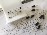
I’ve got hold on matched quad of 2SK170BL matched at 5,8mA.
I bought the Jupiter copper foil in wax 1uf and Mundorf Silver Gold in oil 10uf and replaced them on the card.....really nice.
Then I tried to build one hardwired from the original drawing and it worked!
I used a Blue Alps that I had laying in my workshop. Now I’m planning the final version, with 10X1000uf SILMIC II, z-foil resistors for r102/104-r202/204 and the rest will be a mix of Holco and AMRG.
Next step will be a stepped attenuator, I’ve had a Khozmo in a previous project and it was really nice, but I’m considering going with Seiden this time. Will it be worth the extra bucks?
Casing will be a custom work but that will be a even latter issue.
This unit is extremely quiet, no hum no hiss, nothing except music. I use it with a F7 and 107db efficiency Avantgarde Acoustic Uno Fino Edition.
I’ve got hold on matched quad of 2SK170BL matched at 5,8mA.
Attachments
-
 5E182621-E026-4CDD-8A5D-3549A9F75E09.jpeg802.1 KB · Views: 404
 -
 7D04FA8D-62D3-4E17-8B65-CF6E483B0A53.jpeg705 KB · Views: 374
 -
 20AC4E41-8E8C-44D8-B9B9-0C9156EE2127.jpeg558.3 KB · Views: 353
 -
 E17E1C87-FDC4-4327-A388-9A51D45CA4C3.jpeg604.9 KB · Views: 339
 -
 F405B61B-54C4-4CE8-AA64-70518B953EC8.jpeg461.5 KB · Views: 346

Adagio,
Seeing your B1 wired using pins on a board took me back 50 years when I was a kid, I wired my first 50 watt mosfet amp the same way. I could not afford the Maplin pcb so I built an experimental amp this way and followed with my own pcb.
Pass B1 uses some 1M ohm resistors for bias. One being critical.
Your board will have many unintentional 1M resistors between pins.
This might have an affect on the circuit.
The components you use show that you have no restriction on spending compared to the benifit in sound quality.
My advice to you is go for the pcb with the two matched pairs of the jfets offered by the diyaudio store while its still available.
The link will be there in one of the posts of the past.
Jfets are classed grade A, B, C etc according to the current.
Highest current ones are the best but currently not available.
Higher the current better the dynamics.
Instead choose the second grade closer to 10ma and 2 matched pairs.
No need for a matched quad fot the B1.
Only do not mix the matched pairs. Use one pair each for left and right.
The power supply also plays an important part in noice.
Use a good one sensibly.
Since you plan to put every thing inside a box the pcb is important as the closed box will make the buffer even less noisy.
Enjoy the B1 !
John.
Hi John!
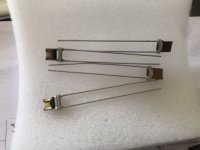
Thanks. The choice to make a hardwire version had nothing to do with price. I like the sound from many hardwired units I’ve had in my system, like Cary audio, Airtight among others. The copper leads are 7N cryo copper and the nails are no magnetic brass. I’m gonna use the 1M z-foil on this early version I had 10K 0,5% matching but not as the original drawing, it’s on the insides next to the J-det instead. This doesn’t really matter at all if it is in series with a cap. If it’s before or after that is. I’m not found of PCB, hardvire ptp is much shorter signalway.
Well any day now my 2SK170 BL quad will come, matched at 5,8mA. This is a no cost limit project for me. It’s for fun and I will not hold back on any level.
Wow!
Nice to hear a difference of openion.
My tube amp friends insist that the hardwired tube amps are superior to pcb types in every aspect including sound.
So after all there is some truth in it !
Nice to hear a difference of openion.
My tube amp friends insist that the hardwired tube amps are superior to pcb types in every aspect including sound.
So after all there is some truth in it !
Perhaps a matter of opinion more than truth. The truth is always subjective with us humans not purely objective. But yes I’m one of those who really are in to hardwired
Hi B1 guys,
Yesterday came across this.
Burning Amp 2017 - Nelson Pass - YouTube
Prof. Papa is getting 6db gain with B1 by adding a transformer to the output.
Existing B1's could be modified to this, with a rotary swith to bypass the transformer if you dont need the gain.
There is also a thread discussing the Transformer B1 in the Diyaudio forum.
What Interesting ideas Papa comes with!!
Hi All
I wanted a simple, low component preamp and decided on the B1.
I bought a board and FETs from PassDIY. I already had some components ( capacitors, resistors) from building loudspeakers years ago. Of course, when the boards arrived, none of these would fit! So, I decided to build it point-to-point. It was my first electronics project, so it was educational (to say the least!) trying to build it from the circuit diagram. Anyway, after a little trouble shooting, I have a preamp that seems invisible to me, so I am delighted.
However, an enclosure has now arrived from China and I'd like to rebuild the amplifier using components bought to fit the board. I really don't want to cannibalise the original to recover the FETs, so am asking about available substitutes. I know the established opinion is to buy another board and bits from Pass, but the original board and semiconductors cost £85 delivered to the UK. I can probably match FETs from a group, but don't know what to order...
Any help would be greatly appreciated..
If you are happy with the B1 then order a new set with matched jfets and pcb for £ 85.
Use only 20k stereo vol control. No other value. Don' get fooled by the Alps blue with knerled shaft or the 2Sk170 bl offered in the China ebay. Those are fakes !
Once you have the new B1 running; start experimenting with all the junk found in the net with your spare pcb. Some people dont listen.They only learn by making mistakes. After all we live in a free world.
Don't worry!
Be happy!
Good luck with your B1!
marec, I think the idea suggested by ItsAllInMyHead is great.
Since you got your hardwired B1 in full swing, you could afford to play around with a experimental B1 while enjoying the one in operation.Also you got a working B1 as a reference to compare your results. Thats great!
So let me offer my second tip.(my 2cents worth).
In the B1 you get a 1M resister from the gate of the upper fet to the 9volt supply rail.
From that point connect a 1M resistor to the ground rail too.
This idea I confermed by applying reverse engineering from Papa Nelson's later version of the B1 namely the Korg Neutube B1. There papa connects 221k ohm restors like I have suggested in his new circuit.
While experimenting, this resistor helped me a lot by taking away the hash when slightly mismatched jfets had to be tried out.
I have spoken about this in detail in the past post #621 of this thread.
Have the cake and eat the cake! What a good idea!
Thanks guys
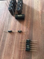
Sadly, I don't have the technical knowledge to select alternatives for myself. I've been trolling through the data sheets and have come across the ON (fairchild?) J112 which might have IDss in the right range, but I can't interpret the transconductance info. And there are probably other parameters, obvious to others, which render it totally unsuitable. But I don't know and am now too old a dog!
Srian, I read your mod earlier in the thread. When I'm confidant I understand the impact the buffer is having, I'll certainly give it a try!. Incidentally, why are you so definite about the Pot value and having it as a stereo Pot? I've already fitted a dreaded ALPS blue 50k!
Here is a source for small quantities of the Linear Systems parts.
LSK170B-TO-92 | LINEAR SYSTEMS | NAC Semi
LSK170B-TO-92 | LINEAR SYSTEMS | NAC Semi
marec,
The j112 or j113 jfets will not work with your original Pass B1 board because their pin outs
differs from that of the Toshiba jfets.
You can build buffers with these parts with some selection and degeneration.
Papa has done that in the B1 Korg and the crossover projects:
http://www.firstwatt.com/pdf/art_diy_nutube_preamp.pdf
http://www.firstwatt.com/pdf/art_diy biamp_6-24_ crossover.pdf
But for your PCB, you need Toshiba jfets or their Linear System replacements.
marec,
First I used an Alps blue 50k log stereo vol. Control which I got from China ebay.
Within a week it gave trouble, though at the time of installation worked well.
Then I replaced it with a cheap Chinese unbranded stereo vol. control of the specified value of 20k log.
I noticed a marked improvement in the trebles and started hearing bell chimes whiched I never knew there was in the music before. My old CD's which were kept away as dull came back to life!
B1 is such a wonder to me.
Then about the interchanging the legs of the Toshiba jfets, one should be very careful to connect the gate properly. I have by mistake interchanged the source and drain of 2SK170bl several times but never come across any problems. This happens because the gate is center leg and when you install the fet numbers facing you or the other wayyou interchange the source and drain.
Then, in one old Toshiba jfet data sheet I came across that you could interchange the source and drain without any issue to performance.
Incidentally, why are you so definite about the Pot value and having it as a stereo Pot? I've already fitted a dreaded ALPS blue 50k!
I have two B1 preamps - one with dual mono 50kOhm GoldPoint attenuators and one with 25kOhm TKD 2CP-2511. Both sound identical through my various FirstWatt, Dynaco, Audio Research and TI TPA3255EVM power amps, so I'm not sure I can detect any difference due to the change in impedance. Note: I used an Alps Blue 50kOhm before added the GoldPoints. It worked well, but the GoldPoints provide more accurate tracking, especially at lower volume levels.
Last edited:
Any more experiences on different impedances of the vol.control at the imput of the B1 ?
Any more experiences on log or linear pots at the input ?
Any more experiences on transformer volume control (TVC) at the output instead of the volume pot at the input ?
DIY is open to discussion of all experiences to optimise the final product !
Any more experiences on log or linear pots at the input ?
Any more experiences on transformer volume control (TVC) at the output instead of the volume pot at the input ?
DIY is open to discussion of all experiences to optimise the final product !
- Home
- Amplifiers
- Pass Labs
- B1 preamp build thread