In my setup, my B1 is followed by an AlephJ built with the PCB from the DIYAudiostore.
Is it safe to remove the 10µF output cap from the B1? I presume the 1µF cap on the input of the AlephJ will do the job, but I prefer to be sure.
You will still need the 10µF output cap in the B1. The 1µF cap in the Aleph J is on the negative input which will be grounded when using the B1. The positive input will pass DC from the B1 if you remove the 10µF which will be a bad thing. 😱
Is it safe to remove the 10µF output cap from the B1?
No. Not at all. It must remain, do not remove.
The B1 is powered from a single rail and approximately 1/2 of the DC power supply voltage is always present at the output. You must have the coupling cap to block the DC and let the AC (music) pass to the next device.
100k alps log pot with loudness tap pre-driven with 10db gain into 10db gain after pot.
works better then any linear pot.
works better then any linear pot.
How about measuring DC at the output?
I'm having over 100mV to start - it decreases to few mV during a couple of minutes.
Should I be concerned - I still havn't conected it to the power amplifier - I would like to hear your view on this before I further.
I'm having over 100mV to start - it decreases to few mV during a couple of minutes.
Should I be concerned - I still havn't conected it to the power amplifier - I would like to hear your view on this before I further.
Output of B1 is DC protected by 10 uf capacitor.
If you measure output without loading, it will show a small eratic stray charge at switch on and specially at switch off. Digital meters are prone to this. When you connect the low impedance power amp to the B1 it will dissapear and you will not hear any clicks or thump at switch on and off.
If you measure output without loading, it will show a small eratic stray charge at switch on and specially at switch off. Digital meters are prone to this. When you connect the low impedance power amp to the B1 it will dissapear and you will not hear any clicks or thump at switch on and off.
Output of B1 is DC protected by 10 uf capacitor.
If you measure output without loading, it will show a small eratic stray charge at switch on and specially at switch off. Digital meters are prone to this. When you connect the low impedance power amp to the B1 it will dissapear and you
will not hear any clicks or thump at switch on and off.
Thank You!🙂
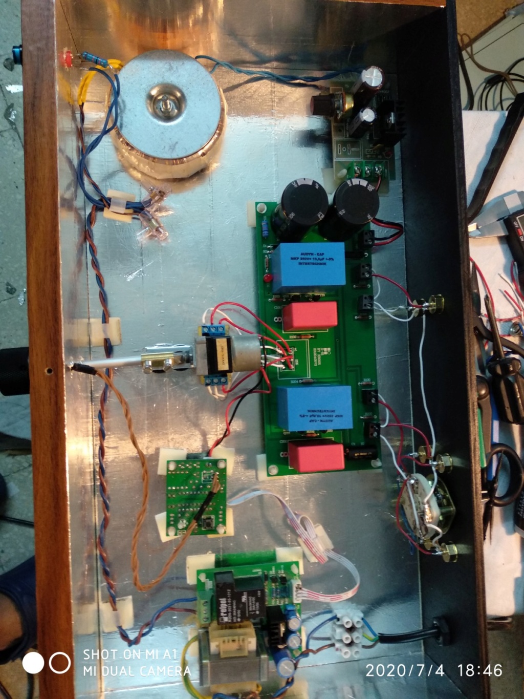
I tried to connect B1 to an existing old setup (equipment of no value, that I wouldn´t be too sorry to destroy).
B1 is singing. Next step is enclosure.
Now let the magic begin... you will not be disappointed.Thank You!🙂
I tried to connect B1 to an existing old setup (equipment of no value, that I wouldn´t be too sorry to destroy).
B1 is singing. Next step is enclosure.
Hello,
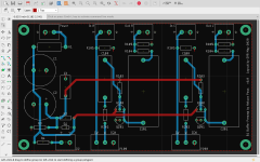
I'm working on a PCB layout for the B1 as a way to relearn Eagle. I've done some very simple PCB's in the past but haven't worked on anything until recently. Would anyone care to critique my layout and make some suggestions if something should be done differently.
A couple of notes,
-C1 and C2 are 10,000uF to save a bit of space.
-I've left out R100/R200 since I will only be using a single input.
-I have all the traces on the bottom layer with the exception of two power traces.
-The ground plane is on the top layer and as uninterrupted as possible.
-I'll be powering it with an 18V wall wart. Since there is no safety earth connection, should I tie the mounting holes to the ground plane like Nelson did with his boards?
-The main concern I have is the length of the input traces running the the pot connections. Could this cause an issue?
-The wire stubs on the top layer all go to ground. I've left the first photo without the ground plane flooded to show the traces and connections to ground better.
I've attached a couple of images. Any help would be greatly appreciated!
-Sam
Attachments

R102/202 is to prevent oscillations in the gate of jfet.
That is needed.
Input should have an input vol control P100 either in the pcb or externally.
Its a must.
If I were you I would supply regulated power from LM317 as used by Papa Nelson in the H2 generator circuit, after the Wall wart. Believe me it will be more silent.
Other than that I havent checked your cct for mistakes.
John.
If less than 10" long input wires could be twisted pairs like in Kat 5 cable.
If more use shielded wire.
Same with output wires.
This is a buffer, wire length no problem, only hum is the problem.
If more use shielded wire.
Same with output wires.
This is a buffer, wire length no problem, only hum is the problem.
R102/202 is to prevent oscillations in the gate of jfet.
That is needed.
Input should have an input vol control P100 either in the pcb or externally.
Its a must.
If I were you I would supply regulated power from LM317 as used by Papa Nelson in the H2 generator circuit, after the Wall wart. Believe me it will be more silent.
Other than that I havent checked your cct for mistakes.
John.
Thanks for the advice. I'll look into adding an LM317. You think this will be beneficial even with a regulated supply?
-Sam
Depends on how quiet your 18v wall wart is!
Any way you have to start with 20+ volts if you intend to use LM317.
If done properly the B1 should he dead silent.
You should not hear any hum when you place your ear in front of the speakers.
John.
Any way you have to start with 20+ volts if you intend to use LM317.
If done properly the B1 should he dead silent.
You should not hear any hum when you place your ear in front of the speakers.
John.
Hi guys, I have completed my motorized Pass B1. I ask for a power supply information from 18 to 24 (as said by PAss) Volts DC. I put 18 volts, but if I put 24 volts do they have differences on the sound? thank you
Take a look at the power supply from the Whammy DiyAudio project; its excellent. The supply Wayne designed measures really well and should be suitable for what you need perhaps with some modifications to get the higher voltage you need.
thanks .... for reply, but my curiosity and to know if there is a difference, sound, with 18 volts power supply, or 24 volts
Is there a difference in sound, with 18 volts power supply, or 24 volts ?
I powered my B1 with LM317 adjustable regulator.
I tried increasing voltage from 18v to 24v.
What I found was at 18v sound was fantastic and the jfets were cool to touch.
At 20v sound was same but the jfets were warm to the touch.
At 24v the jfets started to be very hot with no audiable difference to the sound.
The lower jfet in the B1 is a current regulator.
Increasing voltage does not increase current but turns the excess into heat
dissipation untill the limiting value reaches and after that thermal runaway causes the jfets to burn.
The subjective feedback is important, but did you measure any differences in noise, distortion, etc at the output based on the different voltage levels?
- Home
- Amplifiers
- Pass Labs
- B1 preamp build thread