great, my B1 is now up and running. seems the reverse voltage really didn't do any harm. thanks for all your support!
as a fellow newbie who just finished a B1 I'll try to share some expirience:
Try reading post #497.
The description on the passdiy site says to use 18-24 volt. I guess you should be fine.
+ from the supply goes to the switch and on to + on the board. minus goes straight to the board. make sure not to reverse voltage (as I did!)
1) Most of the LEDs I've found specify 3.5VF and 5VR. Is R4 intended to step down the voltage for the LED? If not, what is it for and do I need to find a different LED for this project? Any suggestions?
Try reading post #497.
2) The power supply I accidentally purchased is 24V (GST120A24-P1M Mean Well USA Inc. | Power Supplies - External/Internal (Off-Board) | DigiKey). I'm assuming this needs to be replaced with something like this: GSM60A18-P1J Mean Well USA Inc. | Power Supplies - External/Internal (Off-Board) | DigiKey. Is this correct?
The description on the passdiy site says to use 18-24 volt. I guess you should be fine.
Which board do you have? On my board they are labelled "+" and "G". You can check continuity with you multimeter and if the blank ones are all connected I'd say the are ground 😀3) On the board the holes for the input switch are labeled L1/R1, L2/R2 and blank. It seems obvious that L and R are channel left and right, respectively, and 1 and 2 are input 1 and 2, respectively. What are the unlabeled holes, the ground?
Try this picture for wiring the switch.4) I'd like to add a power switch. I believe that the PS + goes from the center pin of the input barrel to the in of the power switch, and from the out (on) of the switch of the power + on the board. At the same time PS ground goes directly from the outer pin of the input barrel to the unlabeled power hole in the board. Is this correct?
+ from the supply goes to the switch and on to + on the board. minus goes straight to the board. make sure not to reverse voltage (as I did!)
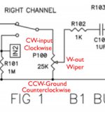
i have no clue.5) And my last newbie question for today: why are the CW and CCW inputs for the volume switched between the left and right channels?
Last edited:
Mixi,
Thanks for the response. It looks like my LED and PSU (if somewhat overkill) are ok.
As for the board (I have the current one from PassDIY) I'm asking about where the switch goes into the board not where the inputs go into the board. I wanted to use a rotary switch to change inputs instead of a toggle and was trying to figure out how to wire the switch. The switch you show in the example has six pins, three each for #1 and #2 inputs. I believe those pins go to left, ground and right, respectively. I haven't been able to figure out how to use a rotary switch in this application instead of a toggle. Any ideas?
I'm guessing that the CW and CCW volume inputs are switched for symmetry on the board, but i'm not sure which of CW or CCW is + and which is -. I recall seeing this described in on the older posts but I haven't been able to find that post again. Any ideas where I might be able to find that post?
Thanks,
Sov,
That's perfect because it helps me understand how the board relates to the schematic and the assembly.
One more question: there are six holes for the input switch, l1, l2, r1 and r2, as well as two unlabeled holes. What are the unlabeled holes, the ground? This isn't obvious to me from the schematic. From looking at the back of the board, however, it looks like the unlabeled holes send some portion of the signal to the input to volume pot (cw), while l1 or l2 takes the + from the left input 1 or 2 and r1 or r2 takes the + from the right input. What am I missing? I guess I'm struggling to go from the schematic to the board, and I really want to know how this works as opposed to just copying another build.
Many Thanks,
... or maybe it is better to say it this way: when l1/r1 are a engaged by the switch it appears that the + signal goes from input l1/r1 to switch l1/r1 and then through the switch to l-cw/r-cw via the unlabeled switch holes. I don't see the path of - going to the switch and it is my understanding that the circuit needs to be on a closed loop. If I wanted to wire the preamp for three inputs I could jump l1/r1 with the unlabeled holes at the switch so that the number 1 input was always on inside the board and the wire the + and - sides of the input RCAs through a switch and back into the board at input l1/r1. In this example the + and - go through the switch. Using the board as it is printed, however, the - never appears to go to the switch. What am I missing? Thanks
l1, r1 are input 1.
l2, r2 are input 2.
the unlabeled ones are the output (left channel on "l" side, right on the other)
do you have a digital multimeter with continuity test (the "beep" thing)?
it really helped me understand the layout as you can check how the solder points connect.
l2, r2 are input 2.
the unlabeled ones are the output (left channel on "l" side, right on the other)
do you have a digital multimeter with continuity test (the "beep" thing)?
it really helped me understand the layout as you can check how the solder points connect.
so my own B1 is up and running but there's some noise that i guess shouldn't be there.
i've read about hum/buzz problems here and it does sound more like the 120hz hum/buzz. maybe a bit higher pitched. it doesn't change with the setting of the volume pot. actually it's still there after turning off the B1 (but still connected to my amp).
any ideas?
i've read about hum/buzz problems here and it does sound more like the 120hz hum/buzz. maybe a bit higher pitched. it doesn't change with the setting of the volume pot. actually it's still there after turning off the B1 (but still connected to my amp).
any ideas?


The lid makes it even more lovely.
Crossing interconnects with unshielded power cable can give a buzz but mostly 60Hz.
How is the power amp wired?
Crossing interconnects with unshielded power cable can give a buzz but mostly 60Hz.
How is the power amp wired?
no difference at all. 😡
in that case , route power wires twisted , away from signal wires
twist all signal pairs/groups in logical way
- Home
- Amplifiers
- Pass Labs
- B1 preamp build thread