I have question about Firstwatt B1 with transformer (from burning amp 2017).
B1 has Cinemag CMOQ-4LPC but can I use Edcor PC 600Ω/15K a or Monacor LTR-110 ?
Monacor: LTR110: LTR-110 - - Monacor Polska Sp. z o.o.
Edcor: EDCOR - PC Series
B1 has Cinemag CMOQ-4LPC but can I use Edcor PC 600Ω/15K a or Monacor LTR-110 ?
Monacor: LTR110: LTR-110 - - Monacor Polska Sp. z o.o.
Edcor: EDCOR - PC Series
Attachments
Last edited:
600 to 15K will give you too much gain , if you're looking for line stage
monacor is closer to proper winding ratio , even having few options more
for 7E/piece certainly worth trying , you can always buy other type , hoping for better
monacor is closer to proper winding ratio , even having few options more
for 7E/piece certainly worth trying , you can always buy other type , hoping for better
Why do you want to add an autotransformer to the B1 version 2?I have question about Firstwatt B1 with transformer (from burning amp 2017).
B1 has Cinemag CMOQ-4LPC but can I use Edcor PC 600Ω/15K a or Monacor LTR-110 ?
Monacor: LTR110: LTR-110 - - Monacor Polska Sp. z o.o.
Edcor: EDCOR - PC Series
swap JFets between channels ..... that's all is left to do
or test suspicious ones (search for JFet matching - all you nee is 9V battery or something like that)
wire twisting and pairing is not in any way connected with your issues
more or less hum is completely another coin ....... and mentioning that now is of great help , obviously
Outch. I would have preferred not to unsolder the J-Fet. To afraid of damaging them...
Well, I don't really have the choice. I'll test the suspicious ones rather than swapping between channels. Left channel's J-fets work well, it will a shame to damage them.
Why do you want to add an autotransformer to the B1 version 2?
because I need more gain. my cd and dac has 0,4-0,5V RMS, my amp is Aleph J, my speaker has 86db sensivity (small monitors)
600 to 15K will give you too much gain , if you're looking for line stage
monacor is closer to proper winding ratio , even having few options more
for 7E/piece certainly worth trying , you can always buy other type , hoping for better
thanks I'll check it
That would be extremely unusual.because I need more gain. my cd and dac has 0,4-0,5V RMS, my amp is Aleph J, my speaker has 86db sensivity (small monitors)
CDP and DVD have maximum outputs of 2Vac to 2.4Vac.
0.4Vac to 0.5Vac would be more typical of average levels from these digital sources.
Have you downloaded Pano's sound files to do any measurements of the signals coming from your digital sources?
Last edited:
Outch. I would have preferred not to unsolder the J-Fet. To afraid of damaging them...
Well, I don't really have the choice. I'll test the suspicious ones rather than swapping between channels. Left channel's J-fets work well, it will a shame to damage them.
.....do you have a dmm?
measure all voltage drops in both channels and compare them.
perhaps this can give you a hint..........
I have a DMM, so I can do that.
I have to measure the voltage across each resistor? In AC mode? Input shorted?
(sorry if my questions are stupid)
I have to measure the voltage across each resistor? In AC mode? Input shorted?
(sorry if my questions are stupid)
......in dc mode (your psu is dc).
measure some points on the pcb........the psu voltage,
the volts at the point where the output cap and the
transistors are connected together and sowhat........
measure some points on the pcb........the psu voltage,
the volts at the point where the output cap and the
transistors are connected together and sowhat........
#366
?
did you tested JFets ?
Didn't have the time to do it.
I found this picture:

Is it OK for testing mine? What am I suppose to read and the DMM?
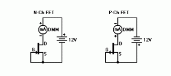
better to use a 100r resistor plus the battery.
Use the diagram in post375 and replace the mA (milli-ammeter) with the 100r resistor.
Set the DMM to voltmeter 20.00Vdc.
Short the Nchannel jFET Gate to Source. You can use a crocodile clip to clip these two legs together. Take that croc clip lead to the -ve of the 9V battery.
Clip your DMM voltmeter across the 10r resistor.
Clip the top of the resistor to the +ve of the battery.
Touch the other end of the resistor to the drain lead of the Nchannel jFET. The DMM reading will change from 0.00Vdc to ~1.00Vdc.
Untouch and reset the DMM to 2.000Vdc.
Touch and read ~1.000Vdc.
The DMM reading can be converted to an equivalent current, using Ohm's Law I=V/R
V=1.013Vdc
R=99r7
Id=1.013/99.7 = 0.01016A = 10.16mA
That is the Drain current when Vgs=0volts.
The Vds is battery voltage - volts drop across the 100r resistor - volts drop on the test leads.
Thus Vds ~9V - 1.013V - ~0.001V = 7.986Vds
If the Vds were 10V and the junction temperature inside the jFET were 25degrees C, then the Id would by definition be the Idss.
Your approximate Id is close enough.
Last edited:
That would be extremely unusual.
CDP and DVD have maximum outputs of 2Vac to 2.4Vac.
0.4Vac to 0.5Vac would be more typical of average levels from these digital sources.
Have you downloaded Pano's sound files to do any measurements of the signals coming from your digital sources?
I checked output levels
TDA1541 + SRPP 6111wa = 1 Vrms
TDA1543 + PASS D1 I/V = 0.8 Vrms
TDA1541 + AYA2 I/V = 1.5 Vrms
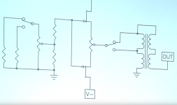
I want to build push pull 2sk170/2sj74 with gain stage and input selector but switchable for 3 options
- only input selector
- input selector + jfet buffer
- input selector + jfet buffer + gain
And I do not know how to connect transformer. Is this correct (transformer is EDCORE 600/10k 1:4 ratio) ?
Attachments
Last edited:
I checked output levels
TDA1541 + SRPP 6111wa = 1 Vrms
TDA1543 + PASS D1 I/V = 0.8 Vrms
TDA1541 + AYA2 I/V = 1.5 Vrms.............
Have you downloaded Pano's sound files to do any measurements of the signals coming from your digital sources?
- Home
- Amplifiers
- Pass Labs
- B1 preamp build thread