VDC?
You said 0vac. If that was 0vdc then we have a serious problem somewhere. Measuring across R9 should be around 2VDC lower than the main +DC rail voltage. If you measure 75VDC across the main power supply caps then R9 should be approx 73VDC if all is well.
If you have a DBT then use it while taking these measurements. It will drop the DC rail voltage but it may limit any damage from a slipped probe. Just let us know you used the DBT while taking the measurements so we can allow for that.
VDC?
You said 0vac. If that was 0vdc then we have a serious problem somewhere. Measuring across R9 should be around 2VDC lower than the main +DC rail voltage. If you measure 75VDC across the main power supply caps then R9 should be approx 73VDC if all is well.
If you have a DBT then use it while taking these measurements. It will drop the DC rail voltage but it may limit any damage from a slipped probe. Just let us know you used the DBT while taking the measurements so we can allow for that.
Yes, I always use the variac/dbt on stuff like this ... not that I do much. But I don't want to take any chances.
I am measuring VDC. #2 is measuring -1.051v
Leave the Black ground probe on the pin in the picture and move your positive probe to the + post on the positive rail capacitor, the big can capacitor in the power supply. What is your VDC reading there?
87.5???
Move your red probe to the negative rail capacitor in the power supply what is that one reading? Leave the grabber attached to the bottom of R9 like in the pic.
Move your red probe to the negative rail capacitor in the power supply what is that one reading? Leave the grabber attached to the bottom of R9 like in the pic.
I can use the same point at R9 and probe neg and pos screw on power supply??
Yes.
I'm trying to figure out where your voltage drops are located.
Next leaving the black grabber attached to the bottom of R9. Move your red probe to a ground screw on either of the two large capacitors. Does it read 0VDC or nearly 0VDC.
Next leaving the black grabber attached to the bottom of R9. Move your red probe to a ground screw on either of the two large capacitors. Does it read 0VDC or nearly 0VDC.
My measurements were on each of the screws of the large power filter cap ...
I need to learn what the neg/pos rails are, if I gave you the wrong measurement.
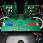
Leave the black grabber on the bottom of R9 and touch your red probe to any point on the ground strip, a screw, solder joint anywhere. You should see close to 0VDC.
Leave the black grabber on the bottom of R9 and touch your red probe to any point on the ground strip, a screw, solder joint anywhere. You should see close to 0VDC.
Yes, 0VDC on both ... I'm hoping this means the power filter caps are ok.
Last edited:
Okay one thing thing I'm concerned with is why your DC rail voltage is so high especially if you have a DBT installed. This is a big concern especially if you have 75VDC rated capacitors.
Does your variac have a 120VAC & 140VAC switch? If so is it set for 120VAC?
Does your variac have a 120VAC & 140VAC switch? If so is it set for 120VAC?
Okay one thing thing I'm concerned with is why your DC rail voltage is so high especially if you have a DBT installed. This is a big concern especially if you have 75VDC rated capacitors.
Does your variac have a 120VAC & 140VAC switch? If so is it set for 120VAC?
No switch. I had it turned up to 120VAC.
DBT has 100w bulb.
I just realized why you are concerned the voltage is higher than the rating on the power supply caps ... hmm ... is this the job of the rectifier?
Wow, thats a crazy high DC voltage even if the transformer is unloaded as in both channels disconnected the voltage is really high. The schematic I posted earlier says the ST202+ should have 75vdc on the rails. I could see it going up to 76 - 78VDC maybe unloaded, but not 87.5vdc.
Unless someone accidently retapped the transformer for 100VAC service at some point in the past. I noticed on the picture of the transformer you posted before that it is a multi-voltage selectable transformer. According to the transformer rating plate it should be putting out 43VAC X 2. Oh well we'll return to that a bit later.
Turn your variac down to where you're measuring about 75VDC across the +DC rail cap to bring the volts down to a safe level for the main caps. We'll have to find out whats going on here later.
You should be measuring +87VDC at Point 2 on the picture I posted last night. Unless you blew the +DC rail fuse on the bottom of the power supply board if not then you either have an open positive rail wire or trace on this board.
I said 87VDC on point #2, that voltage will drop to whatever you set your variac too, 75vdc if thats where you set it.
Turn the amplifier off and let it discharge the main capacitors completely.
Set your meter for Ohms then measure the two leads shorted out to make sure your leads are good. They should measure < 1ohm shorted. Now with the amp powered off and fully discharged put your positive probe on the +dc rail screw (refer to earlier picture) and put your ground probe on point #2 on the channel board, how many ohms are you reading? It should be < 1ohm.
Set your meter for Ohms then measure the two leads shorted out to make sure your leads are good. They should measure < 1ohm shorted. Now with the amp powered off and fully discharged put your positive probe on the +dc rail screw (refer to earlier picture) and put your ground probe on point #2 on the channel board, how many ohms are you reading? It should be < 1ohm.
- Status
- Not open for further replies.
- Home
- Amplifiers
- Solid State
- B&K ST-202 Plus :: hum