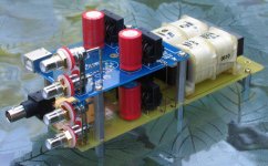
If you compare them, you may notice that both DACs share the PS and output section, only the input circuits are different.
To convert SPDIF to USB you would need to change front end PCB, using existing PS section. You can still use same TDA1543 chip with a regulator, local bypass caps, I/V resistors and output caps.
And if you want to have both DAC inputs, you could build an asembly with two front end boards powered from a single PS (inputs and outputs are completely independant, shared supply includes transformer, rectifiers and C1/C3))
A front end board is available separately at $30.
Attachments
Peter Daniel said:The front end board will work with any DAC chip that accepts I2S input (TDA1543, TDA1541)
Thanks, Peter. I'll have a look at my dacs.
KT
LM3875 & HYPEX SMPS
Peter,
I cannot resist trying to get an opinion from you on the above combination.
The voltage would be slightly high at plus/minus 35 volts.
Do you think there could be anything good to come out of such an arrangement?
Still enjoying my amps. Always hoping for a way to make them a little better, even though I do not have a complaint!
Hope all is well for you.
Thanks,
Rick McInnis
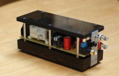
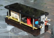
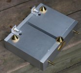
Peter Daniel said:Here's another idea for DAC partial chassis: it provides some extra protection as well better looks.
yes it does look good, nice work peter.
i just started working with lexan. cuts better on the table saw
than aluminum.
")
Attachments

troubleshooting just completed DAC
I just completed audiosector's spdif dac. Looks great; but doesn't work. I'm sure the fault is mine. Since many in this forum might be familiar with this project, I thought I would ask, "How would you go about troubleshooting this project---starting with the simplest tests to more complex test?" If I could narrow down the problem, I could perhaps just replace a few parts and get the thing working. Thank you.
I just completed audiosector's spdif dac. Looks great; but doesn't work. I'm sure the fault is mine. Since many in this forum might be familiar with this project, I thought I would ask, "How would you go about troubleshooting this project---starting with the simplest tests to more complex test?" If I could narrow down the problem, I could perhaps just replace a few parts and get the thing working. Thank you.
Most problems arise from poor soldering.
After verifying that its not your source and not your digital interconnect (in other words use a different source and digital interconnect to verify) then I would flip the dac over and check EVERY SINGLE SOLDER CONNECTION. Start with the power supply and move on down. Each one must look very shiny. I (with the advice of Peter Daniel) also use Rosin Soldering Paste flux on each and every connection. You can get Rosin flux from several places, but I got mine from Radioshack. Apply the rosin flux to the joint, heat up the joint, the rosin will melt, and then apply the solder onto the joint (not the soldering iron) and wait for it to melt. Only use enough solder that is necessary, don't make a glob! Especially problematic areas are where the SMD chips are soldered, such as the CS8412, etc...check every little connection.
The link for Rosin flux at radioshack is: Rosin Soldering Paste Flux
Using Rosin Soldering Flux will make better joints as the solder flows very easily into the joint, especially those tiny holes. Prevents cold joints.
Hope this helps.
Anand.
Re: troubleshooting just completed DAC
Check the voltages after all 4 regulators: it should be 3 x 5V and 8V. If that reads fine, the only other problem is bad solder joint, especially on CS8412 chip.
I offer free of charge repair service for anybody who can't make the DAC running. I had 6 such DACs sent to me already and all of them had bad solder joint
tfrei said:I just completed audiosector's spdif dac. Looks great; but doesn't work. I'm sure the fault is mine. Since many in this forum might be familiar with this project, I thought I would ask, "How would you go about troubleshooting this project---starting with the simplest tests to more complex test?" If I could narrow down the problem, I could perhaps just replace a few parts and get the thing working. Thank you.
Check the voltages after all 4 regulators: it should be 3 x 5V and 8V. If that reads fine, the only other problem is bad solder joint, especially on CS8412 chip.
I offer free of charge repair service for anybody who can't make the DAC running. I had 6 such DACs sent to me already and all of them had bad solder joint
- Status
- This old topic is closed. If you want to reopen this topic, contact a moderator using the "Report Post" button.
- Home
- More Vendors...
- Audio Sector
- AudioSector-chip amp kits, dacs, chassis