Perry which rectifier do you recommend putting the lamp in series with the negative or positive rail or does it matter?
Is that directly on the rectifier?
Is part of the voltage difference due to the lamp?
5 turns is a starting point and is generally enough but not set in stone.
Is part of the voltage difference due to the lamp?
5 turns is a starting point and is generally enough but not set in stone.
Should i do a separate winding for each rectifier?
Because when they share the winding the positive rail is higher but if I do 1 rectifier at a time the voltage is closer to being the same.
Because when they share the winding the positive rail is higher but if I do 1 rectifier at a time the voltage is closer to being the same.
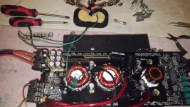
I don't know how complete the circuit is so I can't say what's causing the problem. Post a photo of what you have.
Yes that's directly to both rectifiers the lamp is not in circuit yet I'm trying to get the voltage where I needed first.
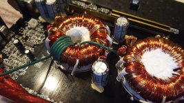
I have five turns around the Transformer one end to the secondary ground the other end is in between the two rectifiers.
the rectifier on the right is the positive rail and a rectifier on the left is the negative rail.
the rectifier on the right is the positive rail and a rectifier on the left is the negative rail.
Attachments

I didn't connect it to the capacitors because I tht the voltage had to be 15v+/- before I moved further so should I connect it to the caps?
You can connect virtually any cap (10uF, 100uF, anything, pull from junker if you need to) from the output of the rectifier to the secondary ground.
Perry you lost me brother I'm very confused at this point sorry I'm just having a hard time following what's happening.
I thought I had to get the voltage to 15+/- then run the lamp in series with one of the rectifiers and the output of the rectifiers would go to the rail caps.
I thought I had to get the voltage to 15+/- then run the lamp in series with one of the rectifiers and the output of the rectifiers would go to the rail caps.
Generally, I suggest the limiters in both rails, connecting this to the main board (caps in the main board) and them powering up. No one has ever tried doing it piecemeal. Having the limiter in only one rectifier should still be safe.
If you want to get the ±15v off of the board, you'll need to connect some capacitors between the rectifier output and the secondary ground. Without any capacitance, it may be making the meter read wrong.
If you want to get the ±15v off of the board, you'll need to connect some capacitors between the rectifier output and the secondary ground. Without any capacitance, it may be making the meter read wrong.

I'm sorry Perry I don't want to frustrate you I'm trying to make it work but I'm just having a hard time understanding.
So I'm going to try and get a power supply that will do15v+/- and get back to you once I do is that okay?
So I'm going to try and get a power supply that will do15v+/- and get back to you once I do is that okay?
- Status
- Not open for further replies.
- Home
- General Interest
- Car Audio
- Audiopipe AP1500D issue