Yes I know it's not in protect at the moment I took the rail caps out do you want me to take the measurements again with it in protect.
The previous Gate Drive signals I sent you pics of was with the amp powered on with no rectifiers, rail caps, outputs in it that's the only way I can get it to power up
The previous Gate Drive signals I sent you pics of was with the amp powered on with no rectifiers, rail caps, outputs in it that's the only way I can get it to power up
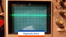
On the highside Probe ground on Source leg and probe on the gate I get a little over 1 volt see picture below.
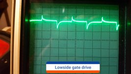
On the lowside Drive if I put the probe ground to -12 volt terminal I get what's shown in the low side pic below.
If I take the low side Drive with the probe ground on the source leg the amp goes in protect as soon as I touched the source leg with the probe ground.
On the lowside Drive if I put the probe ground to -12 volt terminal I get what's shown in the low side pic below.
If I take the low side Drive with the probe ground on the source leg the amp goes in protect as soon as I touched the source leg with the probe ground.
Attachments
Okay looking at the driver board with the ic's facing me starting from the farthest left pin.
The 5 volt Regulators are not in circuit .
Pin 1: -0.004
Pin 2: 0.001
Pin 3: 3.134
Pin 4: -11.43
Pin 5: 11.36
Pin 6: 0.004
Pin 7: 0.004
Pin 8: 0.001
Pin 9: 0.004
Pin 10: 0.004
The 5 volt Regulators are not in circuit .
Pin 1: -0.004
Pin 2: 0.001
Pin 3: 3.134
Pin 4: -11.43
Pin 5: 11.36
Pin 6: 0.004
Pin 7: 0.004
Pin 8: 0.001
Pin 9: 0.004
Pin 10: 0.004
Oh ok lol that would help sorry I took them out while troubleshooting and didn't put them back in so ill put them back in and redo the output drive waves.
5V Regulators reinstalled same drive wave forms as before.
I redone driver board pin voltage measurements
Pin 1: -0.003
Pin 2: 0.001
Pin 3: 3.126
Pin 4: -11.43
Pin 5: 11.15
Pin 6: 0.154
Pin 7: 0.153
Pin 8: 0.001
Pin 9: 4.905
Pin 10: 0.293
Pin 11: 0.292
I redone driver board pin voltage measurements
Pin 1: -0.003
Pin 2: 0.001
Pin 3: 3.126
Pin 4: -11.43
Pin 5: 11.15
Pin 6: 0.154
Pin 7: 0.153
Pin 8: 0.001
Pin 9: 4.905
Pin 10: 0.293
Pin 11: 0.292
Last edited:
Actually on the high side Drive with probe ground on the source leg and the probe on the gate leg it's reading
0 volts instead of 1.2 volts as it did before.
But as far as the low side nothing has changed whatsoever
0 volts instead of 1.2 volts as it did before.
But as far as the low side nothing has changed whatsoever
Ok with black lead on 12v ground I get 4.9 volts on the output legs of u8,u10.
But on u9 on the output leg I get 15.59vdc
But on u9 on the output leg I get 15.59vdc
Last edited:
Yea on u9 with black lead on 12v Ground Terminal I get.
21.79 on input leg
10.46 on ground leg
15.53 on output
21.79 on input leg
10.46 on ground leg
15.53 on output
Measure the voltage on the SMD regulators with the black probe on the tab of the regulator.
Confirm that Q21 (near the speaker terminal) has it's collector directly connected to terminal 3 of the driver board. If so, lift it.
Confirm that Q21 (near the speaker terminal) has it's collector directly connected to terminal 3 of the driver board. If so, lift it.
Ok Perry testing the 5v regulators as you said and they all check out all have 11.4v on the input legs and 4.9, 5v on the output legs.
As far as q21 with my dmm on continuity mode I don't get continuity from the Collector of q21 and pin 3 of driver board header.
As far as q21 with my dmm on continuity mode I don't get continuity from the Collector of q21 and pin 3 of driver board header.
You need to find what's driving pin 3 high. It needs to be at 0v for the driver board to produce pulses.
Ok so pin 3 of the driver board header is connected to The Collector pin on q21.
I wasn't getting continuity on the meter because it goes through a zener diode d32 and a SMD capacitor c40.
But with the amp powered on I have 3v coming from The Collector On q21 through the zener diode D32 and capacitor C40 directly to Pin 3.
So should I pull q21?
I wasn't getting continuity on the meter because it goes through a zener diode d32 and a SMD capacitor c40.
But with the amp powered on I have 3v coming from The Collector On q21 through the zener diode D32 and capacitor C40 directly to Pin 3.
So should I pull q21?
Last edited:
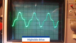
Okay I pulled q21 and the 3 volts on pin 3 of the driver board header is gone.
The low side Drive still looks about the same probe ground on -12 volt terminal and Probe on low side Gates.
1v 10us x10
The high side there is a waveform now probe ground on Source pad and probe on high side gate pad.
5v 5ms x10
Pics below of waveforms
The low side Drive still looks about the same probe ground on -12 volt terminal and Probe on low side Gates.
1v 10us x10
The high side there is a waveform now probe ground on Source pad and probe on high side gate pad.
5v 5ms x10
Pics below of waveforms
Attachments

Last edited:
What does the signal look like on the output (pin 6) of the optocouplers? Ground the scope to the source leg for each side when scoping the output.
What does the signal look like on pins 10 and 11 of the driver board?
What does the signal look like on pins 10 and 11 of the driver board?
- Status
- Not open for further replies.
- Home
- General Interest
- Car Audio
- Audiopipe AP1500D issue