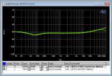
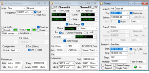
You can also use a transformer as the injection device. AP showed this in one of their application notes but it doesn't seem to have made the transition with the new owners. I have used a Jensen JT-123-BLCF as shown in the AP note.
With any test setup, you have to calibrate to create a compensation curve which takes into account the impedance of the cables etc. Not difficult to do with the AP.
With any test setup, you have to calibrate to create a compensation curve which takes into account the impedance of the cables etc. Not difficult to do with the AP.
Thank you. I am currently trying to use a power amp to drive the bus voltage, but when I try to change amplitude of the disturbance, the plot changes significantly even though I have one channel of the analyzer to the input of the supply of the regulator0 I introduce the regulate the ripple voltage frequency and seems to address.
I will use IRF610 since I have it on hand I will compensate with the PSU in for the loss on the Mosfet.
I will use IRF610 since I have it on hand I will compensate with the PSU in for the loss on the Mosfet.
Last edited:
The Omicron-Lab PSRR procedure uses -10dBm, or 70.7mV as stimulus. If the PSRR is very high, but noisy, you can increase the stimulation voltage.
Application note from TI -- this one uses a common mode transformer to eliminate ground loop effects: https://www.ti.com/lit/an/slyt547/slyt547.pdf
I was reading that application note. It uses the J2120A line injector to inject noise with the generator to the supply, input of the analyzer the DC blocker which I don't get why they DC BIAS Injector J2130A followed by the common mode transformer J2102A all coupled with 50ohm connections.
While this shows an incredible noise range, it is also extremely costly. I was considering the J2130A for Bias injection, but the power amp with the High pass filter seems to work but I don't know how reliable the results I am getting. Below is the result on the Jung Regulator I am adopting which clearly has problems.

To validate, I will also implement the circuit you proposed and see if I get the same result. I will post later today.
While this shows an incredible noise range, it is also extremely costly. I was considering the J2130A for Bias injection, but the power amp with the High pass filter seems to work but I don't know how reliable the results I am getting. Below is the result on the Jung Regulator I am adopting which clearly has problems.
To validate, I will also implement the circuit you proposed and see if I get the same result. I will post later today.
I tried the circuit but unfortunately it doesn't work. I am assuming the high output impedance of this stage makes it unsuitable to drive the low impedance supply rails of the regulator which has several electrolytics.This works quite well, minimal parts. You don't want to suffer the unfortunate consequences of placing a large DC signal on the Analog Generator of the AP.
There is a way of using a gate driver IC to create the Vgs on the MOSFET. Otherwise you lose that voltage across the MOSFET. Choose a MOSFET with low-ish Vgs(th)
View attachment 1351294
I am currently using the amplifier method suggested by Duke that works along with the regulation feature on AP.
With capacitors at regulator input, there is a question of required current from injector to impose sine wave voltage across capacitor. For standard 120 uF and 100 mVrms, at 20 kHz, above 1A is required.I tried the circuit but unfortunately it doesn't work. I am assuming the high output impedance of this stage makes it unsuitable to drive the low impedance supply rails of the regulator which has several electrolytics.
Proposed injector can provide rising voltage, but can’t decrease charge from the capacitor. That has to be provided by regulator load (about 200 mA max.?) or by placing adequate load in parallel with regulator input.
Best practice during test is to remove input capacitor, if regulator is stable without and expected PSRR doesn’t rely on that capacitor. If not, then to try with smallest capacitor that provides stable operation.
you are correct, but the regulator is on the main board already. However, since I am fixing the regulator itself, I can always remove the input filtering caps.
I will have to dive then into the reason as to why the Jung regulator has that poor PSRR, but first I need to make sure my measurement is correct and consistent.
I am going to remove the caps and repeat the test.
I will have to dive then into the reason as to why the Jung regulator has that poor PSRR, but first I need to make sure my measurement is correct and consistent.
I am going to remove the caps and repeat the test.
Last measurement of the night as it's past midnight. As I am measuring the LM7815 to baseline my measurements, I obtain this ugly plot

Long story short, as I am debugging these results, I find out that the response of the amplifier is very NOT linear at all which is affecting dramatically the results.
I will go ahead and order the line injector tomorrow as I don't have any small linear amp laying around to run those tests and I would have to buy a decent one and might cost just as much as the line injector itself.
Look at the many 'R' characters at the top of the graph.
That indicates that the regulation has not been completed for that step.
(A 'T' would indicate a time-out).
It seems there is a problem with the test setup.
Is that sweep setting for Data1 correct?
Jan
That indicates that the regulation has not been completed for that step.
(A 'T' would indicate a time-out).
It seems there is a problem with the test setup.
Is that sweep setting for Data1 correct?
Jan
Texas Instruments suggests eliminating the electrolytics in front of the regulator if you want to see the DUT doing its thing.I tried the circuit but unfortunately it doesn't work. I am assuming the high output impedance of this stage makes it unsuitable to drive the low impedance supply rails of the regulator which has several electrolytics.
I am currently using the amplifier method suggested by Duke that works along with the regulation feature on AP.
Thanks for the input. Now I do understand what R and T means. It cannot regulate because the retarded amp I picked up at goodwill has two outputs for low and high and the response of the amp on the lows is this thus the reason it cannot regulate.

gotcha. I am going to remove the electrolytics in front of the Jung regulator on my board for testing purposes and re-run the 7815 using the mosfet to inject the signal.Texas Instruments suggests eliminating the electrolytics in front of the regulator if you want to see the DUT doing its thing.
View attachment 1351723
I tried with the mosfet injection and while the closed loop system can regulate, there is self-oscillation that is skewing measurements. BTW I will go return the "amp" at goodwill as it is only taking space ahahahLook at the many 'R' characters at the top of the graph.
That indicates that the regulation has not been completed for that step.
(A 'T' would indicate a time-out).
It seems there is a problem with the test setup.
Is that sweep setting for Data1 correct?
Jan
thanks for the info, I have added 2.2uF at the output of the regulator for stability I go with the regulation feature (only one point it couldn't regulate within 1% but the graph matches yours very closely. Thank you again. I use the DSP simply because I can set the bandpass for more accurate reading I can see it is not necessary.

I will next, remove the electrolytics from the board and make a measurement on the Jung reg using the Mosfet injection.
I will next, remove the electrolytics from the board and make a measurement on the Jung reg using the Mosfet injection.
Sorry I had missed this part. I saw in fact the tech note from TI where they calibrated for cables, but I don't know how to do it with AP, I will look into that as well, but as of now, even without the compensation, the curve comes in very close and reliable.You can also use a transformer as the injection device. AP showed this in one of their application notes but it doesn't seem to have made the transition with the new owners. I have used a Jensen JT-123-BLCF as shown in the AP note.
With any test setup, you have to calibrate to create a compensation curve which takes into account the impedance of the cables etc. Not difficult to do with the AP.
btw are you using the 2522 or the 2722? I can see you have AP2700 SW interface 🙂
Yes it is!! It is still darn close to the APx555.
I just say I love the 2522, I don’t get people who prefer sound cards lol I have sound card and left it in the corner. Low noise measurements repeatable easy to use fully protected, you can’t get wrong for audio measurements! If I had the money I would have gone for the 2722 but it is significantly more expensive thiight it offers about 3dB of improvement which is definitely nice step up to mine!
I wonder if it has the same hardware with some “simple” changes or it is a completely different boards!
Finally, I was able to measure of the Jung Regulator on board with the electrolytic removed, I need to figure out why I have worse performance with the electrolytics connected.

This is the noise floor of the setup I am having, which seems pretty adequate to measure the regulator.

This is the noise floor of the setup I am having, which seems pretty adequate to measure the regulator.
- Home
- Design & Build
- Equipment & Tools
- Audio Precision SYS2522

