I am an engineer too but what you are missing and should know, is that the field of precision instrumentation especially when it comes to FFT and ultra low distortion, is a nitch that requires specific set of skills. Calculations in the frequency Romanian, mantissa, aliasing and many other factors come to play to give you a true e realistic spectrum and to minimize digital noise. With that said, even if I understand crude specifications like you, and I believe you are very good as well, someone who works specifically in this field, might explain in details the difference involved behind a precision low noise instrument for measurements and a mere 100 bucks sound card. A low noise digital generator taken by a dac won’t ever be practically comparable in terms of noise to an analog ultra low noise/distortion generator such as the one sported by apx555B. I am not equipped to give you a very detailed answer, but a sound card gets really stupid low numbers on the program, you have to ask yourself how real these numbers are vs how much of an artifact and I think AP has sorted this out. In the end, maybe you are right I don’t know but it would be great if someone that works in this field can chime in and explain what we are missing.
Meanwhile enjoy your setup and if someone wants to give you a 555 since you don’t like it let me know I give you my address!! Thanks 😊🥳
Meanwhile enjoy your setup and if someone wants to give you a 555 since you don’t like it let me know I give you my address!! Thanks 😊🥳
you, guys, are too romantic, this is not an engineering approach. I just said that APs are too noisy to measure modern DACs, even $3 CS43131 with 550nV(A), APx555(with residual noise 700nV(A)) shows as 123db(A) of DR instead of 130db(A). Cirrus Logic released a special appnote kinda "how to get promised specs with APx555" with the schematic of external LNA 😉

I just tested CC with REW wonderful results! A bare Cosmos ADC grade A may notice the difference of ES9039Q2M MCLK 49 vs 24.5MHz, -130db(A) vs -129.4db(A)!Cross correlation seems to be a very efficient method for lowering noise in ADC/DAC measurements.
https://www.audiosciencereview.com/...-influence-of-adc-for-dac-measurements.56123/
REW beta now has cross correlation.
THD+N is also very close to APU's result -125.8db vs -126db, a bit worse due to the ADC unit has H3 -138db. The fantastic result anyway!
now try with your 2522 😉 ....btw as we speak, I am making measurements on my project, so we connect the two 2522 in remote and in duo tandem they become more powerful.
APs can not be ported to the REW, so no CC for AP users 😉 However, your EMU card may use REW's CC.
My EMU card is connected to SoectraPlus works good too, or maybe not so much anymore lol…I think the day before buying the AP unit, which could be a sign that I needed a full conversion to AP’s family 😂, I blew up the input of the sound card when I forgot, for the first time in years, to disconnect it when I powering down the phono prototype!!
Anyway hopefully it still works it’s a legacy card for me I had it for several years.
One thing the EMU on laptop is better than AP+APWIN, is the speed of analysis where I can average 64 with 128K samp almost IN real time while it will take about 2min to process 1 scan of 32k samp with 5000points and 64AVG. 😅😅😅
Soundcard vs. Audio analyzer-
Soundcard (today) amazing frequency response and THD across its operating range. Low noise (when operated at optimum levels and impedances). However fragile input, essentially fixed input level and limited frequency rage (typically 100 KHz)
Audio analyzer Protected differential input Wider dynamic range (at least max input) wider frequency range, measurement to 500 KHz or even 1 MHz for level and noise. Stand alone operation in many cases.
Different audio analyzers are focused to specific applications. They started as a tool to meet FCC brodcast performance for AM transmitters high harmonics would generate interferance with adjcent AM stations. IM analyzers were important for the movie industry for ensuring correct operation of optical audio tracks. Then the HiFi industry in the 1950s becam enamord of measurements (thanks to Julian Hirsh et. al.). However the key customer driving the requirements was the US military with fat contracts.
AP analyzers are great if you want to automate a series of tests or test al the i/O's of an AV receiver without moving cables. On an bench they are OK. However they don't have a lot over a self contained analyzer (e.g. Shibasoku or Panasonic) if you are troubleshooting a broken amp or new design.
The QA analyzers are a great solution offering most of an AP's basic capabilities for less than the software licence for AP. The practical limit of the QA is the max input at 30? volts. The convience of an integrated analyzer/software really helps move the process along.
The soundcard/software benefit is the option of different software, each having specific advantages. REW seems to be the go to for soudcards. I like the analysis capability of DiAna https://www.diyaudio.com/community/threads/diana-a-software-distortion-analyzer.315785/post-5266519 that is only matched by the Shibasoku analyzers.
There is no single solution for an audio analyzer. That why I have 8 different analyzers. (Or my poor rationalization for the collection.)
WRT noise- there are specific limits on noise. Its a function of bandwidth (any noise claim without measurement bandwith is meaningless), source impedance and temperature. On an analyzer getting low noise and input protection are mutually contradictory and will always be a compromise. You can get lower noise (ref Cirrus app note) without protection. Not a good idea for a general purpose instrument.
Chasing ever lower distortion is an interesting pursuit. At some point its no longer meaningful for audio. The serious research suggests .1% is probably the best case threshold but thats old research. However getting any acoustic link that low or lower is really difficult and impractical.
More important is knowing how to use the instruments and when they are lying to you. If the number is too good or too bad its probably a lie.
Fully agree with your analysis, especially the tradeoff protection vs vanishing input noise and whether we need this extremely low noise for audio design. This is why I think AP is a good solution as it presents very low noise with excellent protection and lots of integrated/automated testing.
QA403 was on the top list at one point, but I ended up going for a very good price AP.
Personally, I think it is exactly like you said it, it is about knowing how to use and interpret the results more than anything, when they are too bad or too good to be true, most likely they are not 🙂
Thanks again for your post it helped me putting things in perspective.
I thought sharing what I'm using might help. Its an AP S1 (without digital) with the IM, Wow and Flutter, and Burst options. Its working fine (I had to replace some parts fried by a previous user). Its connected to a PC running win 10 32 bit. Along with a vintage picoscope (parallel port interface). With this vintage setup (basically 20 years old) I can get good insights into almost any audio device. For digital I have an EMU 1212 in the same box. All up it might cost $1400 for the hardware (and hours of fiddling to get it working). The AP S1 performance is limited by the JFet switches. The later AP's use relays. Its not a big enough issue for me to replace it.
It doesn't do much that a QA403 would do, even the Wow and Flutter analysis can be had with a QA403 I believe.
If the hardware were not given to me I would be using a QA403 or similar. The large waveform and spectrum are nice after using 7" tek scopes.
I have both a Shibasoku 725 and a Cosmos ADC if I need to look at lower distortion. And if really important I have the Radiometer CLT-1 with a -170 dB distortion residual. Nice but not useful or important for normal work.
This prompted me to think about some protecting attenuator I will attach to my sound card in the near future.I blew up the input of the sound card when I forgot, for the first time in years, to disconnect it when I powering down the phono prototype!!
This is the idea:.
Attachments
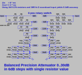
Obviously good idea to add attenuators to protect the input of your sound card. Problem with that the, one source impedance grows thus noise goes up, also impedance changes and your measurement levels get out of calibration. But for rough measurements and protection is a good simple solution.
Thanks for sharing!!! That’s a very good thd+n figure. In fact even S1 holds down wonderful specifications even though it’s an even older piece of equipment. Truth is, low noise was handled already in the 80s, in fact, the best semis with lowest distortion and noise were made back then. Nowadays only opamps which have gotten good but still discrete circuit with the hitachi BJTs will have the edge.I thought sharing what I'm using might help. Its an AP S1 (without digital) with the IM, Wow and Flutter, and Burst options. Its working fine (I had to replace some parts fried by a previous user). Its connected to a PC running win 10 32 bit. Along with a vintage picoscope (parallel port interface). With this vintage setup (basically 20 years old) I can get good insights into almost any audio device. For digital I have an EMU 1212 in the same box. All up it might cost $1400 for the hardware (and hours of fiddling to get it working). The AP S1 performance is limited by the JFet switches. The later AP's use relays. Its not a big enough issue for me to replace it.
It doesn't do much that a QA403 would do, even the Wow and Flutter analysis can be had with a QA403 I believe.
If the hardware were not given to me I would be using a QA403 or similar. The large waveform and spectrum are nice after using 7" tek scopes.
I have both a Shibasoku 725 and a Cosmos ADC if I need to look at lower distortion. And if really important I have the Radiometer CLT-1 with a -170 dB distortion residual. Nice but not useful or important for normal work.
View attachment 1350059
What is the FFT on the left?
Not necessarily a real problem. The source impedance is in my example <2k for the soundcard and could be optional reduced by choosing other resistor.Problem with that the, one source impedance grows thus noise goes up, also impedance changes and your measurement levels get out of calibration. But for rough measurements and protection is a good simple solution.
The noise contribution is neglible compared to the intrinsic noise of the Codec.
At least in the case of my Motu M4 with heavily modified input stage.
Its the Picoscope. Its an 8 bit 100 MHz PC scope with parallel port from 1998 or so. Its really all you need. The software in this case is limited to a 4K FFT. Later Picoscopes working with USB have higher resolution options. However I hate discarding fully functional and useable stuff. The cheapest Picoscope on eBay would work fine. The Pico software is the best USB scope software I have used. 8 bits is more than enough after the analyzer has preprocessed the signals. I tried a 16 bit Picoscope which brought nothing to the measurements (except not enough bandwidth). Getting this all on a 24" monitor makes it much easier to see what is happening.What is the FFT on the left?
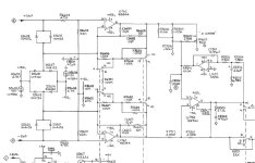
You need to add some clamp diodes to protect the input. Best practice seems to be light bulbs in series to limit the current (but have low resistance when off) and diodes clamping to the rails. The input protecting for the AP S1 is below. You can see the light bulbs (48V in this case) and the clamp diode array Bruce Hofer used. It seems to work quite well. It could be simplified some.This prompted me to think about some protecting attenuator I will attach to my sound card in the near future.
This is the idea:.
Attachments
What I meant to ask is what signal is that FFT?Its the Picoscope. Its an 8 bit 100 MHz PC scope with parallel port from 1998 or so. Its really all you need. The software in this case is limited to a 4K FFT. Later Picoscopes working with USB have higher resolution options. However I hate discarding fully functional and useable stuff. The cheapest Picoscope on eBay would work fine. The Pico software is the best USB scope software I have used. 8 bits is more than enough after the analyzer has preprocessed the signals. I tried a 16 bit Picoscope which brought nothing to the measurements (except not enough bandwidth). Getting this all on a 24" monitor makes it much easier to see what is happening.
You also need to add some compensation capacitors to keep the FR flat at high attenuation.You need to add some clamp diodes to protect the input. Best practice seems to be light bulbs in series to limit the current (but have low resistance when off) and diodes clamping to the rails. The input protecting for the AP S1 is below. You can see the light bulbs (48V in this case) and the clamp diode array Bruce Hofer used. It seems to work quite well. It could be simplified some.
Jan
For highest resolution this is the way to go.You need to add some clamp diodes to protect the input. Best practice seems to be light bulbs in series to limit the current (but have low resistance when off) and diodes clamping to the rails. The input protecting for the AP S1 is below. You can see the light bulbs (48V in this case) and the clamp diode array Bruce Hofer used. It seems to work quite well. It could be simplified some.
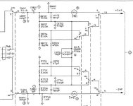
But in my case there are OPA1678 input buffers .
For protetection I added 10k series resistance.
With guaranteed max input rating of +-10mA I do not not need any clamp diodes upto 100Vpp on each branch of balanced input.
The 10kOhm series resistance adds 11nV/sqrt(Hz) to 4.5nV/sqrt(Ht) input noise of OPA1678.
That looks pretty much compared to top notch inputs in the ballpark of 1nV/(ssqrt(Hz).
But in reality input noise of the ADC is dominant, so resolution only degrades a tiny bit.
This is a loopback measurement at -2dB FS generator level.
Attachments
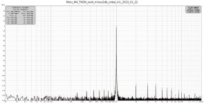
Its the FFT of the residual after the notch filter. Its on the "reading" output.What I meant to ask is what signal is that FFT?
- Home
- Design & Build
- Equipment & Tools
- Audio Precision SYS2522