Hello everyone,
I’m having trouble configuring my Ucpure QUAD to output 3.3 V instead of 5 V. Here’s what I’ve done so far:
Is there another step I’m missing or a common pitfall when switching voltage on the QUAD? Any suggestions would be greatly appreciated. Thanks!
I’m having trouble configuring my Ucpure QUAD to output 3.3 V instead of 5 V. Here’s what I’ve done so far:
- Initial setup
- The jumpers were all open, so the board was set to 5 V by default.
- Switching to 3.3 V
- Powered down the unit (switched off S1 and unplugged).
- Installed four jumpers as per the manual: two on J14 and two on J15.
- Ensured each jumper bridged pins 1–2 and 3–4 correctly.
- Powering back up
- Reconnected and powered on the QUAD and power on S1.
- Reconnected and powered on the QUAD and power on S1.
Is there another step I’m missing or a common pitfall when switching voltage on the QUAD? Any suggestions would be greatly appreciated. Thanks!
I'm looking at the manual, and I don't know what you could have done wrong. Only thing I can think of, is you have the jumper orientation wrong.
I’ve double‑checked the jumper orientation several times and I’m confident it’s correct.I'm looking at the manual, and I don't know what you could have done wrong. Only thing I can think of, is you have the jumper orientation wrong.
Do I need to discharge the capacitors? I’m beginning that process now.
Perhaps it’s necessary to discharge them before switching from 5 V to 3.3 V.
I’d really like to test this power supply at 3.3 V.
Use a automotive 6 or 12 v light bulb to drain the capacitors down to at least 3v
Drain them in series where the lug nuts are to ensure equal voltage on both caps.
Drain them in series where the lug nuts are to ensure equal voltage on both caps.
Helo @Gabster 2000 ,
Thanks a lot for the tip.
So, to run the UcpureQUAD—which was working at 5 V—at 3.3 V, do I always need to discharge the capacitors before switching to 3.3 V?
I’ve been using them at 5 V and the D9 PURE LED is on, so they’re fully charged.
At this point, to make them work on 3.3 V, is it just a matter of draining the capacitors and then adjusting the jumpers?
Correct
I would not bounce back an forth decide if they will be used for 5v Or 3.3v
Check the voltage that it is 3.3 or close to it before connecting them to avoid sending 5v to a 3.3v board and frying it by accident.
Connect the cable to charge between songs and breaks that will keep the voltage from drifting down too much a critical part
The Quad is best used for the FifoPi/clocks 3.3v for the Dac like Dual mono Dac I would rather use 2 separate 5v rather then 1 quad to feed the 2 separate Dac supplies
Hope that helps have fun
@Gabster 2000 ,
Can I leave the 6–12 V lamp mounted on the Ucpure Quad board, or should I remove the caps from the board for do this?
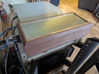
If I do connect the lamp while it’s still on the board, where would you recommend I attach the positive and negative leads, based on this image:

Thankss!!!
Can I leave the 6–12 V lamp mounted on the Ucpure Quad board, or should I remove the caps from the board for do this?
If I do connect the lamp while it’s still on the board, where would you recommend I attach the positive and negative leads, based on this image:
Thankss!!!
You can use either J10 or J13 ( either one they are connected together) these are connected directly to the caps or The easiest remove 2 plastic caps ( 1 + 1- ) on the top main board and put the bulb on any positive and negative.
The 2 banks of Caps are connected in parallel (The 2+are connected together same with the2 -) so you will be draining all 4 caps this way (avoid any shorts your wire will burn instantly and you can burn your fingers if not worse) as there is no fuse on J10 and 13 same for the cap screws you are connected directly to the caps so be careful shorting anything.
Do not leave the bulb permanently this is just temporary to drain them till you get around 3v.
I think most of us same for me the first time i saw it think because there are 2 output terminals that these are 2 independent supplies they are Not they are the same Connected in Parallel The Advantage of the Quad is you have more Storage capacity so they last longer and less voltage drift, also half the ESR. They are Ideal for the FifoQ7 3.3v Clocks or other applications where you want the lowest ESR and bigger storage Capacity
Last edited:

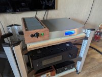
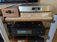
external case for the power supply lumin s1 case also almost ready.
it has a dual pcm 1794A in it and is controlled by an ian canada purepi-ll and a fifoPiMa.
it has a dual pcm 1794A in it and is controlled by an ian canada purepi-ll and a fifoPiMa.
Attachments

I was thinking this might be a little off topic, but on second thought, not really. Long story short, I have an Oppo 103 that plays SACD's and I the RecieverPiDDC, so I can play DSD files. The thing is I don't know much about DSD and a friend of mine gave me the Oppo, and until recently I didn't even know it played SACD's. So I have two basic questions about it. First, I'm assuming if I by tracks or albums from Quboz or similar, do put them on a thumb drive to play locally from a USB to the Pi, and or play from a local hard drive on my local network?
The second question it occurs to me, maybe should be one question I guess. Could someone share some links about DSD and SACD so I read about it. I find myself floundering, and there's so much personal opinion as you all know, I'd like to try to sift through some of that if possible. I'm just wondering about things like, is a downloaded DSD as good as a physical SACD and how do I play a DSD file. I was looking at the Oppo I2S mod that you can get, but if I don't really need physical CD's then it seems the same money could be spent on downloaded DSD's instead of the mod. Although, out of curiosity, I would like to compare the sound of the Ian Canada DAC versus the Oppo DAC on DSD.
The second question it occurs to me, maybe should be one question I guess. Could someone share some links about DSD and SACD so I read about it. I find myself floundering, and there's so much personal opinion as you all know, I'd like to try to sift through some of that if possible. I'm just wondering about things like, is a downloaded DSD as good as a physical SACD and how do I play a DSD file. I was looking at the Oppo I2S mod that you can get, but if I don't really need physical CD's then it seems the same money could be spent on downloaded DSD's instead of the mod. Although, out of curiosity, I would like to compare the sound of the Ian Canada DAC versus the Oppo DAC on DSD.
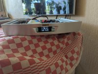
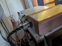
On a smoke color window in front is the pcm 1794A in lumin S1 case ready. Also made a dark blue slaves for the power and gpio (rotary encoder) cable.
it has an ian purepi ll, ucconditioner and a FifoPiMa in it.
I consider it done.
it has an ian purepi ll, ucconditioner and a FifoPiMa in it.
I consider it done.
Attachments
Need some help on assembling the following:
I have all the modules listed in 94B but I'm not clear on the stack and what connections I need to make.
The Pure Pi II is on the bottom and I'm going Piless
The ReceiverPi DDC is on top of that with an Amenero on the bottom. What I'm unsure about is if I'm just supporting the receiver above the Pure Pi so that it doesn't touch anything are am I trying to connect make contact?
The FifoPiQ7II FIFO clocker goes on top with monitor Pi going onto J2
Where does the GPIO extender come into play?
ES9038Q2M Dual Mono II DAC goes on top of the FIFO
Transformer I/V KIT on the top
The Pure Pi II will have the batteries so both the 3.3V and 5V are available. What are all the connections I need to make for power and control?
If you want a DDC and DAC all-in-one solution, you can install a HdmiPiPro II or a TransportPi AES under the DAC PCB in the #94B configuration
https://iancanada.ca/products/flags...citor-and-battery-psus?variant=47628835389740

Ok, so I have the FifoPiQ7 not the II. I'm Pi less, using the PurePi II for power. I have only the 3.3V connected from the PurePi II to the FifoPiQ7 and the DAC hat. I did not connect the 5V from the PurePi II to the FiFoPiQ7. I don't get any display on the MonitorPi Pro. I think I need to connect the 5V but just want to be sure
Success! Yes, connect both the 5V and 3.3V from the Purepi II to the FifoPiQ7 to get it working
Hi @sbelyo
If my understanding is correct, you can get it work with power connections just as
Wall Port 5V 2.5A Power Source to Pure Pi II USB C - Then from Pure Pi II 3.3V to both FifoPiQ7II 3.3V & ES9038Q2M Dual Mono II DAC J1 which is AVCC 3.3V. That's all it needs.
All remaining cards does not need any power source Like Transformer I/V & Receiver Pi DDC ....
After having both the 5V and 3.3V from the Pure Pi II to the FifoPiQ7, how are you connected power to ES9038Q2M Dual Mono II DAC Card?
Could you please share end to end power connection chain you have got in.
Not sure why do we need 5V connection as well from the Pure Pi II to the FifoPiQ7 when you already have 3.3V connection? Will this make any difference from having only 3.3V connection?
Experts, please advise/correct. Thanks in advance.
So here's what brought me to that. I have just the Q7 and not the Q7II. The Q7 requires both 5V and 3.3V. The Q7II requires only 3.3V. Now, if there was a Raspberry Pi in the stack I think it would've carried the 5V needed up through the stack. I am Pi-less sot there is no 5V power coming up to the Q7 and that's why I had to make the connection.
As per my understanding even with Q7 and with out RPi
Wall Port 5V 2.5A Power Source to Pure Pi II USB C - Then from Pure Pi II 3.3V to both FifoPiQ7 3.3V & ES9038Q2M Dual Mono II DAC J1 which is AVCC 3.3V. That's all it needs and should work.
Could you please confirm
After having both the 5V and 3.3V from the Pure Pi II to the FifoPiQ7, how are you connected power to ES9038Q2M Dual Mono II DAC Card?
I also would like to know why do we need 5V connection as well from the Pure Pi II to the FifoPiQ7 when you already have 3.3V connection? Will this make any difference from having only 3.3V connection?
- Home
- Source & Line
- Digital Line Level
- Asynchronous I2S FIFO project, an ultimate weapon to fight the jitter