
Quick report back, success I think. Basically I did two things...
1. Left the batteries to charge completely overnight (I am not aware they were inadequately charged, but I had not checked the onboard LEDs to confirm that so took no chances this time, and those LEDs do confirm now that everything is charged appropriately.
2. I followed the advice of @mvaldes and the lost indicated here, i.e. adding PSU_MAX_CURRENT=5000 to the boot config file. I believe this was the key item, but cannot be 100% certain if the charging level was an issue also.
Otherwise, I used the same charger and nothing else different.
Many thanks to everyone for their assistance and advice. I have not yet fully hooked the FifoMa to the 3.3v power from the purepi, and therefore not yet produced sound from the TransportPi, but I am more confident of that now the basic power appears to be resolved.
9V in my case did well. great deepness in soundstage noticed.Powering the linearPi with higher input A/C voltage.
Ian has the following sentence in the manual of the LinearPi:
“Someone reported that a higher voltage can make the sound quality better.”
Has anyone experimented with this?
6v AC is the correct voltage to use if you have a high continuous current due to lesser differential voltage for the regulator; meaning lesser heat at the heat sink.
But in my case where I am to power the OPA861, current is not an issue…
I only have a dual 9v but not a dual 6v transformer at hand so cannot really test it…
a little late. but. take a look at the ess controller, there is some information about the functions of the dac.I've just installed a ES9038Q2M dual mono II DAC with the OPA861 zero feedback bal I/V board on top an Rpi with FiFOPI Q3
I've also the Monitor PI PRO where there are many setting for the DAC that I can't find any documentation.
I've also removed the DAC clock and I've connected the M/Clock signal from FifoPIQ3 to ESS DAC
Are there suggested setting to use with IAN ES9038Q2M DAC ?
I'm posting the screenshot of the setting I'm trying to figure out how to configure
Any help will be appreciated
https://github.com/iancanada/DocumentDownload/blob/master/ESScontroller/ESScontrollerManual.pdf
I have a question about grounding the Q7 to the Station SMT....in the manual it says s this..."
Connect analog ground of the system or the ground of FifoPi clean side to the EARTH of StationPi
SMT by a grounding wire."
Okay, the ground on the SMT is clearly marked, but I have no idea what the "ground of the FiFoPi clean side" is...unless I missed it, I don't see a ground like on the SMT that I can connect a ground wire too. And a related question...if I am using a UCPure for example powered by a laptop PSU, which isn't grounded anyway, what's the point?
Here it is about wiring, I have the isolatorpi2, fifopima, 9038q2m2.
So I want fifopima to be the master clock, of course.
so if I understand correctly I have to :
* connect isolator to fifopima with the ufl coaxial cables for the I2S, SCK, LRCK and DATA output in addition to the gpio ports?
* and I modify J12 and J13.
* and then from fifopima to the dac the u.fl masterclock cable?
I really looked through the manuals but I couldn't find a clear answer, finally I'm not sure.
Depending on the modules you want to assemble there are details that escape me
So no the only input of the isolator to fifopima even in master clock mode goes through the gpio and it is the setting of the jumpers which gives the choice of the clock. Correct me if I am wrong. If it can help some.
Anybody here used Sparkos Op Amps on an I/V STD Mkll? If so how would it compare to OPA 861?
In my system, OPA861 sounds much better than I/V STD. I have not tried Sparkos Op Amps, but many others, including discrete ones. OPA861 is much better. Just ensure you power it with a high quality power supplies.Anybody here used Sparkos Op Amps on an I/V STD Mkll? If so how would it compare to OPA 861?
I have some spare Ian Canada boards for sale. If someone is interested, please check here: Ian Canada boards for sale
The new FifoPi Q7II comes with new "ultra-low-phase noise XOs." They look quite different than the ones in the FifoPi Q7. Can anyone tell me more about these clocks and specifically whether they are as effective as the Accusilicons and/or Crysteks? Thanks.
@Gabster 2000, thank you for your reply! I have had a very busy summer and fall, and finally getting around to read the replies to my July post. THANK YOU! I will order 2 100va Dual output transformers asap, and then figure out how to wire, switch them, etc. I am anxious to get the project completed, well, at least operational. My initial idea is to mount all this gear on apiece of butcher block or similar, and organize so that the wire runs are the shortest possible. Gaby, I have watched most all of your videos, and you are the inspiration to do this project. I have learned a lot already, even how to solder, but soooo much more to learn. So, thanks again, I appreciate your advice!@Gsabest
The 100va Dual output works great I do not recommend a 50 VA unless it is a single output but then you will need a lot of transformers
I have 1, 50Va dual output and hate it it is too slow.
I keep my UcPures on the Default 3A with no issues that transformer is rated at 4A per output so great margin
I think the main things is your safety layers
1) 3 to 4A fuse on each low voltage AC line
2) A main Fuse for your Transformers High Voltage line
3) Grounding the Transformers (if using the medical grade ones They have a green Ground lead)
4) Grounding the Case
5) Using non flammable wiring
6) Short leads large AWG wire from UCpure output
7) Do not short Fuse on UCPure
8) Soft start if using a switch or Relay to start the Transformers
9) Secure all UCs to the case
10) make sure to use cover screws on the UCs
11) Make sure Transformers are wired correctly for 120, 240 100 .... as a wrong wiring can cause the transformers to heat and burn check the Temperature of the transformers it can easily happen.
12) Cover all high voltage wires and terminals NONE should be exposed.
This is a partial list Have fun and play safe
Gaby
Hello , If i run 2 Linear pi's in parallel will it double the current, so getting 5 amps instead of 2 * 2.5 or will I suffer even more pain than I already have working on this project of mine ? I don't think so as it seems like you would need a balancer or something
I've been using 2 linearpi MKII in parallel with the UcConditioner MkII for a year now and I have no problems.Hello , If i run 2 Linear pi's in parallel will it double the current, so getting 5 amps instead of 2 * 2.5 or will I suffer even more pain than I already have working on this project of mine ?
As a noob...how would one go about troubleshooting no sound at all. I don't know if it's software, I messed up a board by scratch or solder, or I messed up a jumper or something somehow. Was working previously.
Just wondering if there's a way to use my dmm or something to find if I have a signal at the streamer spdf...
Just wondering if there's a way to use my dmm or something to find if I have a signal at the streamer spdf...
I would start by observing what LED's are effected if any. Next I would check voltage on the 3.3 and 5 volt rails, with a multi meter. and go from there. I screwed up a Q3 , I had 5 volt, but not 3.3, with the corresponding LED's not lit up either. Check any fuses as well on your PSU's. I ground my Q3 out and ruined it, and ended up getting a Q7...not an entirely bad outcome, since I got a really good deal from the swap meet on some other things that included the Q3.how would one go about troubleshooting no sound at all. I
Hi guys,
I've been following this thread for quite some time and found it to be so inspiring. This and @Gabster 2000 YT channel lit the spark and made me follow a DIY path - something I've never done before. Thank you all for that 🙂
My initial setup evolved a bit over time, the final one is nothing very fancy but gave me so much fun while putting it all together.
So, I started with RPI4 as an Roon's endpoint with SHIELDPi PRO and powered by ALLO NIRVANA. Next, there was Gustard DDC U18 which fed Gustard R26 via I2S.
I then decided to go with two stacks and got rid of U18:
1/ RPI4 + SHIELDPI PRO + PUREPI II
2/ BRIDGEPI & AMANERO768 + FIFOPI Q7 II with SC-PURE 45 & 49 on board and powered by UCCONDITIONER PRO 3.3V + HDMI PRO II + MONITORPI PRO
The result was encouraging enough (sound wise) to go a step further and make it more like a ready made product.
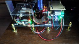
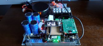
So today I've ended up with a single board solution:
As for the OS, I use jitter and latency optimized Linux RT kernel configuration for RPI with an USB audio output (https://github.com/maniac0r/rpi-usb-audio-tweaks).
The next step is to put it all in a nice case 🙂
I've been following this thread for quite some time and found it to be so inspiring. This and @Gabster 2000 YT channel lit the spark and made me follow a DIY path - something I've never done before. Thank you all for that 🙂
My initial setup evolved a bit over time, the final one is nothing very fancy but gave me so much fun while putting it all together.
So, I started with RPI4 as an Roon's endpoint with SHIELDPi PRO and powered by ALLO NIRVANA. Next, there was Gustard DDC U18 which fed Gustard R26 via I2S.
I then decided to go with two stacks and got rid of U18:
1/ RPI4 + SHIELDPI PRO + PUREPI II
2/ BRIDGEPI & AMANERO768 + FIFOPI Q7 II with SC-PURE 45 & 49 on board and powered by UCCONDITIONER PRO 3.3V + HDMI PRO II + MONITORPI PRO
The result was encouraging enough (sound wise) to go a step further and make it more like a ready made product.
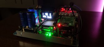
So today I've ended up with a single board solution:
- power: 1182Q6 Hammond transformer + dual LINEARPI 5V & 3.3V + UCCONDITIONER 5V & 3.3V
- stack no. 1: RPI4 + SHIELDPI PRO + BRIDGEPI & AMANERO768
- stack no. 2: FIFOPI Q7 II with SC-PURE 45 & 49 + HDMI PRO II + MONITORPI
As for the OS, I use jitter and latency optimized Linux RT kernel configuration for RPI with an USB audio output (https://github.com/maniac0r/rpi-usb-audio-tweaks).
The next step is to put it all in a nice case 🙂
Attachments
- Home
- Source & Line
- Digital Line Level
- Asynchronous I2S FIFO project, an ultimate weapon to fight the jitter