Does anyone have any idea how to fix MonitorPi Pro on the front panel of a chassis with 4mm thickness?
@melorin Tap screw holes at the appropriate places and use standoffs to secure the PCB to the panel.

In that case (no pun intended) just a washer between the PCB and panel, and screw it in.
My bad on suggesting standoffs. That's not needed.
My bad on suggesting standoffs. That's not needed.

Yes, though it would be nicer to have a round hole for the rotary, since it already has it's own fastener.
I don't own the MonitorPi yet myself, but is the top of the display the same height as the rotary, not the shaft, the part where the fastener is max turned down too.
Having a separate opening for the display would be nicer.
I don't own the MonitorPi yet myself, but is the top of the display the same height as the rotary, not the shaft, the part where the fastener is max turned down too.
Having a separate opening for the display would be nicer.


Maybe the first would work too, just a bigger hole.
In that case the display would not be too far inside the panel.
I would personally like that, instead of being flush with the panel.
In that case the display would not be too far inside the panel.
I would personally like that, instead of being flush with the panel.
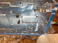
I would go for this “measurement”. I used that when cutting a hole for my MonitorPi pro.
I did it in 6mm acrylic with a laser cutter and was therefore able to cut the shape of the encoder as a hole.
It will also be possible with a CNC in metal. You just have a radius on the slot made for the two taps at the encoder.
Are you to cut the hole by hand by your self or to have it professionally made on a CNC or similar?
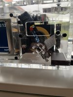
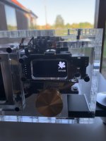
I also removed the encoder to a second location. The location of the encoder on the monitor pi pro limit the size and type of volume button and to me doesn’t look very good.
Here's how the hole looks like (I am waiting for a replacement monitorpi pro. The ESS controller is temporarily):
Attachments
Modushop is excellent. My favorite chassis and parts! They possibly have two sites, one at your link at modu.it, and the other at modushop.biz. Here are the 1U chassis parts (but all are available there): https://modushop.biz/site/index.php?route=product/category&path=33 I'm in the states and shop at the second site.
@iancanada I am in a email conversation with Giastras for a potted toroidal transfomers.
One 6V and two 9V secondary windings.
But he is asking me for the minimal Amp requirement.
The LinearPi MkII manual doesn't mention this at all. I can only find a max because of the 2.5A to 3A fuse that is used.
Could you, or anyone else, shed some light on this, please?
One 6V and two 9V secondary windings.
But he is asking me for the minimal Amp requirement.
The LinearPi MkII manual doesn't mention this at all. I can only find a max because of the 2.5A to 3A fuse that is used.
Could you, or anyone else, shed some light on this, please?
Even though the input max is 3A because above it the fuse will blow?
I know it will only require what is needed, but that can't go above the limit of the fuse.
But what is the minimum?
I know it will only require what is needed, but that can't go above the limit of the fuse.
But what is the minimum?
The linearPi will only draw a maximum of 2,5A (depending on the load attached to the linearPi of course, but a max of 2.5A) even if you but a 100A in front it. The 3A fuse is there if any unwanted case like a short or loaded with excess amount of current, would happen. If you used a 2,5a fuse instead, that fuse would blow when you pulling the max out of the linearPi. This fuse will always have to be slightly bigger.
It is always good practice to have a fuse in front of the transformer at the 230v primary side. Remember that you are at 230v and the current will be much lower.
It is always good practice to have a fuse in front of the transformer at the 230v primary side. Remember that you are at 230v and the current will be much lower.
Last edited:
Me as well, but @melorin even sooner I think 🙂
Totally forgot about that DXF file.
Can find the file here: https://github.com/iancanada/DocumentDownload/tree/master/MonitorPi/MonitorPiPro
Keep in mind, if you're not known with Github, to click the dxf file and then the button "raw" before you download it.
Otherwise you're saving a webpage instead of the DXF file.
- Home
- Source & Line
- Digital Line Level
- Asynchronous I2S FIFO project, an ultimate weapon to fight the jitter