Thanks so much qusp and hochopeper for your quick response and help. Both of you thinking so fast that while I am still trying to understand your first post, there are already several posts follow.
nothing connected to the board? is that a steady value? that seems pretty low given you are measuring across an LC filter with an inductor in series and a 10uf cap to ground. other than checking the parts mentioned above by hochopeper L1, C4, L2 and U3 i'm out of ideas given I dont have schema, or board here. hopefully Ian pipes up shortly, sorry I couldnt be of more help
Yes, nothing connected, just the board alone. With Red to pin 10 and black to pin 9, it read 4.732K. If red on pin 9 and black on pin 10, the capacitor is discharging. reading drop from 4XXK.
Isolation board testing
Isolation board received and populated with the smd parts.
Soldering of the smd parts is OK except the 4 resistor networks which is quite tricky. Their Soldering result has to be double checked to avoid shorting signals to ground through some unused resistors that are connected to.
I will provide a detailed listening result within one week to ensure the Isolation board complete break-in.
In the meanwhile, following a couple of hours running I have noticed a global gain of the DAC transparency i.e. Sound more coherent and natural and an increase of the PRAT. Better dynamics and separation of instruments within a darker background.
I assume this is due to an increase of the S/N of the DAC which, analogue and digital grounds are no more polluted by the FIFO ground noise.
My DAC configuration is a double Mono WM 8741 Opus DAC from TP powered by independant rails and Shunt regulators. The clock is powered by an independant rail fitted with a Bybee MusicRail device.
A design suggestion for the Isolation board would be to add an I2C isolation section to enable connecting an Arduino board to control the DAC while avoiding the pollution of their ground.
Ian, thank you for giving us the opportunity to build state of the art DACs !!
Ian
Received the isolator board yesterday and soldered all the components today. Connected it to FIFO and clock board, use separate batteries (2xLiFe=6.6V) for clock and FIFO. All LEDs "on" but the SPDIF input card not function. Remove the isolator board, everything fine. Voltage to the ICs on the isolator board are 3.2XXV. While still finding the fault, smoke came out from the clock board🙁, a component next to the FIFO letters on fire!!!Looks like a capacitor.
What shall I do?
1. SPDIF board has no buiness with clock board. No function means no correct clock came from clock board to fifo. Check up your isolator board for any possible short, wrong IC P/N, wrong soldering position or ffc cable side or soldering dircetion;
2. If you power the FIFO and Clock board from separat PSU without isolater board in between, certainly the two PSU will short. That why you get the smoke. You have to fix the PCB, I saw the DC5V trace burn up already.
Do not need remove L11 for working with isolator board.
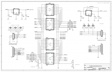
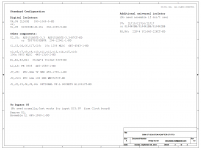
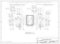
I attach the schematics again for reference.
Always check up for any possible short after maunal SMTA.
Believe you can make it. Don't worry, it's just a small case🙂. Let me know for any help.
Ian
Attachments
Last edited:
A design suggestion for the Isolation board would be to add an I2C isolation section to enable connecting an Arduino board to control the DAC while avoiding the pollution of their ground.
Ian, thank you for giving us the opportunity to build state of the art DACs !!
Ian's actually got you covered for i2c already, that's what U7 is all about!
cracra, you could populate the extra optional isolator (U7 and surrounding components) and make up your own pinout for i2c, thats what its there for, but you have to decide what connects where.
OK bigpandadank, pay no heed to my first post, I dont know enough about the clock board schematic to know if that could be the problem or not, Ians post describes a different situation with direct battery power, but still probably holds true and your problem is likely on the isolator board. lets hope the inductor is the sole victim of this mishap.
apologies for the somewhat acerbic first reply, i'll be watching with interest.
one more: when the isolator didnt work at first, did you then perhaps remove it but absentmindedly leave the boards powered separately while you continued testing?
Ian, but without proper clock communications with fifo due to bad isolator connection, what LEDs would light on the spdif board? would it possibly appear dead, but still be powered? answer my own question, no it wouldnt be affected as it gets clock from the fifo itself.
I was treating the spdif board as a separate issue, one at a time
we need pics!
Last edited:
Thanks Ian1. SPDIF board has no buiness with clock board. No function means no correct clock came from clock board to fifo. Check up your isolator board for any short, wrong IC P/N, wrong soldering position or ffc cable side or soldering dircetion;
2. If you power the FIFO and Clock board from separat PSU without isolater board in between, certainly the two PSU will short. That why you get the smoke. You have to fix the PCB, I saw the DC5V trace burn up already.
Do not need remove L11 for working with isolator board.
I attach the schematics again for reference.
Always check up for any possible short after maunally SMTA.
Believe you can make it. Don't worry, it's just a small case🙂. Let me know for any help.
Ian
Since the L11 already burnt. can I just short the 5V to pin 2 of J4? What is the value for L11?
dont even think about connecting anything to that isolator till you rule out or fix it.
supply your own 5v to pin 9 of J9 and pin 2 of J10, preferably with some sort of current limiting ie, not batteries that can put 140A into a short...
supply your own 5v to pin 9 of J9 and pin 2 of J10, preferably with some sort of current limiting ie, not batteries that can put 140A into a short...
Last edited:
Thanks Ian
Since the L11 already burnt. can I just short the 5V to pin 2 of J4? What is the value for L11?
You can, but I guess L11 still alive, just the trace burn up. Please make sure with a multimeter.
You have to check up your isolator boare with 100% before your next try. That what I'm suspecting.
Ian
Isolation board received and populated with the smd parts.
Soldering of the smd parts is OK except the 4 resistor networks which is quite tricky. Their Soldering result has to be double checked to avoid shorting signals to ground through some unused resistors that are connected to.
I will provide a detailed listening result within one week to ensure the Isolation board complete break-in.
In the meanwhile, following a couple of hours running I have noticed a global gain of the DAC transparency i.e. Sound more coherent and natural and an increase of the PRAT. Better dynamics and separation of instruments within a darker background.
I assume this is due to an increase of the S/N of the DAC which, analogue and digital grounds are no more polluted by the FIFO ground noise.
My DAC configuration is a double Mono WM 8741 Opus DAC from TP powered by independant rails and Shunt regulators. The clock is powered by an independant rail fitted with a Bybee MusicRail device.
A design suggestion for the Isolation board would be to add an I2C isolation section to enable connecting an Arduino board to control the DAC while avoiding the pollution of their ground.
Ian, thank you for giving us the opportunity to build state of the art DACs !!
Good job! Thanks cracra four your update. Congratulations!
I'm looking forward to your testing result on the isolator board and over all system.
There is a optional isolator footprint U7 pleace on the isolator board, may have chance trying the I2C isolator on it 🙂.
Nice weekend.
Ian
I will use bench PSU to test the isolator board before connecting it to the circuit again.
Ian, I already lost the L11!!
Ian, I already lost the L11!!
sounds like a plan. do some probing around with DMM before even doing that, can you set current limit on the bench supply?
sounds like a plan. do some probing around with DMM before even doing that, can you set current limit on the bench supply?
I've checked all connections with DMM. The bench supply has current limit setting. Any suggestion on the value?
Jumped the 5V and pin2, connect the clock back to the FIFO. Power up and everything seems fine. LEDs on and SPDIF working. Not yet connect it back to DAC.
Ian,
Got the isolater board thank you. Looks great - even the board is cut where the isolation occours🙂
I will place the component order for this and the battery management board these days and I also think it is time for me to invest in a dedicated smd rework station (OT: any <200$ suggestions would be welcome by PM)
Cheers,
Nic
Found some from eBay(just found, not for recommendation):
SMD SMT Soldering Rework Station 2in1 Hot Air Gun Iron Welder Tip ESD PLCC BGA | eBay
New 2 in1 SMD SMT Soldering Rework Station Welder Hot Air Iron 852D 220V | eBay
Soldering wires, solder paste and flux are also importatn.
Ian
something about 10ma above the operating current of each side of the isolator chip, say 30ma total for both sides (I presume you will supply both sides with the same bench PSU for this testing?) the input has a quiescent current of 2mA and the output 6mA, then be generous and give the regs 10ma, which they will probably not need. actually which isolator are you using? those numbers are for the NVE part. theres not much by way of capacitance on the board so inrush wont be much of a factor
Jumped the 5V and pin2, connect the clock back to the FIFO. Power up and everything seems fine. LEDs on and SPDIF working. Not yet connect it back to DAC.
Start as low as possible then increase. The 3.3V reg will current limit to 300mA so no point setting it higher than that. Perhaps 50mA or so would be ok starting value.
something about 10ma above the operating current of each side of the isolator chip, say 30ma total for both sides (I presume you will supply both sides with the same bench PSU for this testing?) the input has a quiescent current of 2mA and the output 6mA, then be generous and give the regs 10ma, which they will probably not need. actually which isolator are you using? those numbers are for the NVE part. theres not much by way of capacitance on the board so inrush wont be much of a factor
My bench PSU has two output, so I can use individual output to power each side (15mA). I am using IL260E.
Jumped the 5V and pin2, connect the clock back to the FIFO. Power up and everything seems fine. LEDs on and SPDIF working. Not yet connect it back to DAC.
That confirmed eveything is alive. The next, you have to do 100% check up on your isolator board according to the schematics . Post a picture if possible.
Ian
- Home
- Source & Line
- Digital Line Level
- Asynchronous I2S FIFO project, an ultimate weapon to fight the jitter