Thanks but it didn t give a sound.
Should the aes transport have a red light like the fifopi?
Should the aes transport have a red light like the fifopi?
Have you checked the manual.
You can download from audiophonics.
https://www.audiophonics.fr/en/inte...SNr1UiViHm1bn76yn4668odjgT5DOkFizwS2cTXtZ1r8k
You can download from audiophonics.
https://www.audiophonics.fr/en/inte...SNr1UiViHm1bn76yn4668odjgT5DOkFizwS2cTXtZ1r8k
So, have you been able to complete the build of the Gabster DAC? If yes, what are your impressions? Thanks.Hi @pkonstantinidis, I am also in process to adding TDA1541 DAC in my streamer. I have in my hands the ian canada i2s to PCM converter and I am waiting for IFI power supplies (2X 5V supply plus 2X UCconditioners and a 15V supply plus Gabster CRC Power filter).
For the moment I have a TDA1541 (non A) chip. I am wondering if any colleague has to recommend or share a positive feedback of a reliable TDA1541A supplier (for example from ebay) .
Once DAC is ready I will revert with feedback.
hi @pkonstantinidis,
The DAC is ready. Yesterday, music signal flowed through its RCA outputs. For the moment, I am not in position to comment on sound since I ‘ve just heard it through some low cost headphones only for testing purposes. I also tested it with an non A chip in order to avoid the risk of flying my precious. Now that I know that there is no short circuit, I will use my precious TDA1541A taken from a Proton CD player.
Some comments to help friends that currently building the TDA1541A DAC.
I will hear on my speaker system the TDA with the non A chip and then with the TDA1541A chip and revert with comments.
The DAC is ready. Yesterday, music signal flowed through its RCA outputs. For the moment, I am not in position to comment on sound since I ‘ve just heard it through some low cost headphones only for testing purposes. I also tested it with an non A chip in order to avoid the risk of flying my precious. Now that I know that there is no short circuit, I will use my precious TDA1541A taken from a Proton CD player.
Some comments to help friends that currently building the TDA1541A DAC.
- The guidance provided by @Gabster 2000 is indeed helpful and sufficient. If you just follow instructions from @Gabster 2000 YouTube channel you will not have any further queries.
- Soldering particularly U.FLs and LEDs (provided in 3.3 version) is really challenging. I am not experienced in that, and I received valuable help from a friend (professional of the field) while most of soldering work was undertaken on his bench.
- Speaking about LEDs, please be careful to solder them on with the right orientation, since they operate as diodes.
- On the I2S to PCM board do not forget to put ONLY one jumper on JOB on it. At the same time, be careful with the setup jumpers at the back of the TDA board.
- Further from soldering U.FLs, carefully connect the U.FL cables on the boards. The first time, I connected the TDA, it produced a white noise output. I was afraid that I fried the TDA. I initially removed the I2S to PCM board to see if the TDA would play if connected directly with FIFO PI. But, when I connected FIFO PI with TDA, I forgot to change the setup on the back of the board (fortunately, this did not cause any malfunction). So I did it, I proceeded with the DC offset and music came out. The TDA was working properly. On a second step, I used again the I2S to PCM board. I made sure the all U.FLs were properly connected, I changed the setup on the back of the TDA board. At last, all equipment was working properly!
I will hear on my speaker system the TDA with the non A chip and then with the TDA1541A chip and revert with comments.
Attachments

Hi All, not sure if this is the right forum to appeal for help, but here goes....
I have an Ian Canada streamer comprising of Raspberry Pi 4, mounted on Station Pi, feeding a Fifo Q3 then outputting to a Transport Pi for SPDIF output to a DAC
I added a SinePi v8 a couple of months ago and fed that with an external clock with 11.2896MHz and 12.288MHz TTL square wave outputs, which worked really well.
All good so far, then I chanced upon a pair of TWTMC DRIXO of the same frequencies (11.2896MHz and 12.288MHz) to try out on the streamer.
In short, it does not work with the SinePi, it will not lock onto either 44.1KHz or 48 KHz music files, all that happens is the relay clicking back and forth between the 2 inputs.
If I revert back to the TTL clocks, all is good again!
I have confirmed the DRIXO clock outputs into the SinePi (50 Ohm load), frequencies of 11.2893MHz at 3.92V peak to peak and 12.2877MHz at 4.25V peak to peak.
User manual states;
Input clock amplitude range: 0.5V - 5V Vpp (with 50 ohm termination)
Input clock frequency range: 1-150MHz (sine or square wave)
So, where am I going wrong?
I assume there is a Schmitt trigger or similar built into the SinePI, is this perhaps not working?
Any suggestions would be most welcome.
I have a very similar configuration and the same clocks.
I also had similar problems. Sometimes it worked, sometimes it didn't. After I tried everything, I replaced FiFoPi from Q3 to Q7. The problems disappeared.
I also had similar problems. Sometimes it worked, sometimes it didn't. After I tried everything, I replaced FiFoPi from Q3 to Q7. The problems disappeared.
Hello,
does anybody know if Ian Canada is well?
His Blog is down and the are no answers to eMail. Also there are no posts for about 5 month.
Regards
Branko
does anybody know if Ian Canada is well?
His Blog is down and the are no answers to eMail. Also there are no posts for about 5 month.
Regards
Branko
@TheodorMhi @pkonstantinidis,
The DAC is ready. Yesterday, music signal flowed through its RCA outputs. For the moment, I am not in position to comment on sound since I ‘ve just heard it through some low cost headphones only for testing purposes. I also tested it with an non A chip in order to avoid the risk of flying my precious. Now that I know that there is no short circuit, I will use my precious TDA1541A taken from a Proton CD player.
Some comments to help friends that currently building the TDA1541A DAC.
Final point, I have in my collection many high res files (96kHz and 192kHz, 16bit and 24bit). All were reproduced from the TDA1541 (non-A chip) without any problem. To that end, I see no need to down sample the files.
- The guidance provided by @Gabster 2000 is indeed helpful and sufficient. If you just follow instructions from @Gabster 2000 YouTube channel you will not have any further queries.
- Soldering particularly U.FLs and LEDs (provided in 3.3 version) is really challenging. I am not experienced in that, and I received valuable help from a friend (professional of the field) while most of soldering work was undertaken on his bench.
- Speaking about LEDs, please be careful to solder them on with the right orientation, since they operate as diodes.
- On the I2S to PCM board do not forget to put ONLY one jumper on JOB on it. At the same time, be careful with the setup jumpers at the back of the TDA board.
- Further from soldering U.FLs, carefully connect the U.FL cables on the boards. The first time, I connected the TDA, it produced a white noise output. I was afraid that I fried the TDA. I initially removed the I2S to PCM board to see if the TDA would play if connected directly with FIFO PI. But, when I connected FIFO PI with TDA, I forgot to change the setup on the back of the board (fortunately, this did not cause any malfunction). So I did it, I proceeded with the DC offset and music came out. The TDA was working properly. On a second step, I used again the I2S to PCM board. I made sure the all U.FLs were properly connected, I changed the setup on the back of the TDA board. At last, all equipment was working properly!
I will hear on my speaker system the TDA with the non A chip and then with the TDA1541A chip and revert with comments.
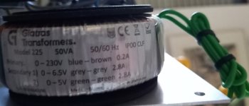
could you please share those used toroidal transformers detailed specs and links please.
White ifi adapter - which config you picked? 9V/2.5A 12V/2A 15V/1.5A ? Black ifi must be 2.5A models.
Also when you get time a rough connectivity diagram will help a lot. Please. Thanks in advance.
I noticed his absence too. This situation is a bit worrying... 😕Hello,
does anybody know if Ian Canada is well?
His Blog is down and the are no answers to eMail. Also there are no posts for about 5 month.
Regards
Branko
Hope he's well.
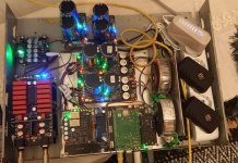
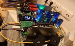
Hi @VMRKarnati ,
The streamer part has two power supplies:
-5V power supply: is the toroid seen in the picture (same as @pkonstantinidis – see pic) using its 6.5V winding -> 5V IAN CANADA LINEARPI MKII ->5V IAN CANADA UCCONDITIONER PRO feeding (1) the 5V side of IAN CANADA STATIONPI PRO plus (2) the Ian Canada I2S to PCM board.
-3.3 V power supply: is the toroid seen in the picture (same as @pkonstantinidis – see pic) using its 6.5V winding -> 3.3V IAN CANADA LINEARPI MKII ->3.3V IAN CANADA UCCONDITIONER PRO feeding the IAN CANADA FIFOPI Q7 II
The TDA part (excl the Ian Canada I2S to PCM board see above):
-2X [ IFI iPower2 5V/2.5A -> 5V IAN CANADA UCCONDITIONER PRO] feeding the TDA -5V/0/+5V output stage
-IFI iPowerX 15V/1.5A -> 2X in raw CRC Filters (proposed by Gabster) feeding the TDA DAC part.
Hope this helps.
Attachments
Last mail from Ian, nov 7th. Hope is well.Hello,
does anybody know if Ian Canada is well?
His Blog is down and the are no answers to eMail. Also there are no posts for about 5 month.
Regards
Branko
Thanks a lot TheodorM for this detailed info. this helps a lot. much appreciated for your help and support!!!Hi @VMRKarnati ,
The streamer part has two power supplies:
-5V power supply: is the toroid seen in the picture (same as @pkonstantinidis – see pic) using its 6.5V winding -> 5V IAN CANADA LINEARPI MKII ->5V IAN CANADA UCCONDITIONER PRO feeding (1) the 5V side of IAN CANADA STATIONPI PRO plus (2) the Ian Canada I2S to PCM board.
-3.3 V power supply: is the toroid seen in the picture (same as @pkonstantinidis – see pic) using its 6.5V winding -> 3.3V IAN CANADA LINEARPI MKII ->3.3V IAN CANADA UCCONDITIONER PRO feeding the IAN CANADA FIFOPI Q7 II
The TDA part (excl the Ian Canada I2S to PCM board see above):
-2X [ IFI iPower2 5V/2.5A -> 5V IAN CANADA UCCONDITIONER PRO] feeding the TDA -5V/0/+5V output stage
-IFI iPowerX 15V/1.5A -> 2X in raw CRC Filters (proposed by Gabster) feeding the TDA DAC part.
Hope this helps.
Is there anybody here who has experience with battery PSU, i have tried to exchange linearpi with a powerbank feeding a PurePI and the difference is great.
- Home
- Source & Line
- Digital Line Level
- Asynchronous I2S FIFO project, an ultimate weapon to fight the jitter