@Yveskoala you got nothing to worry about with the May decoding DSD.
They have a fantastic implementation with their FPGA.
With HQplayer and enough cpu power you could upsample everything to DSD1024 lol.
They have a fantastic implementation with their FPGA.
With HQplayer and enough cpu power you could upsample everything to DSD1024 lol.

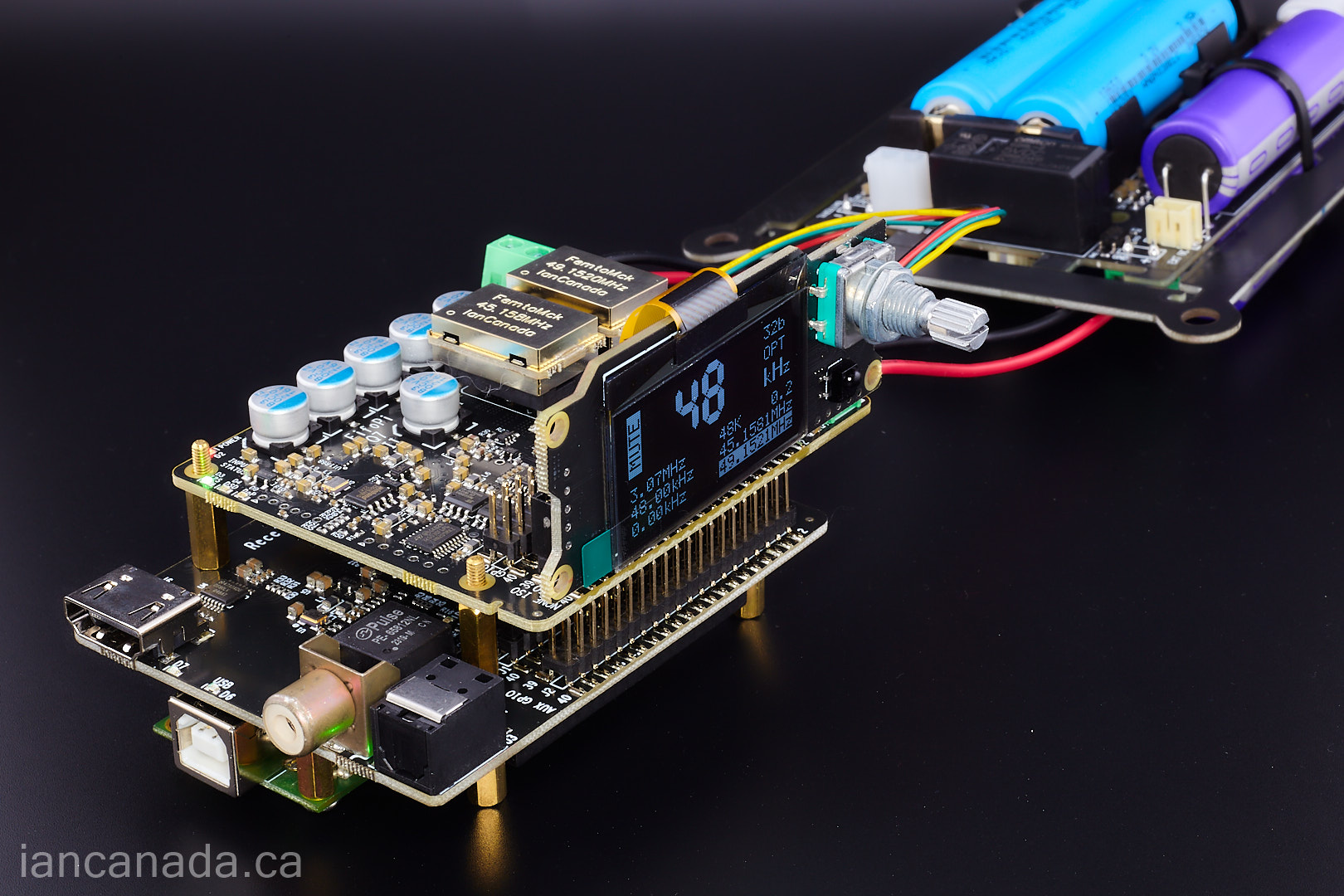
I like this DDC configuration (RPi free). Very clean and very easy to assemble.
1. ReceiverPi DDC
2. FifoPiQ7 II
3. MonitorPi Pro
1. ReceiverPi DDC
2. FifoPiQ7 II
3. MonitorPi Pro
Hi @iancanada ,I like this DDC configuration (RPi free). Very clean and very easy to assemble.
1. ReceiverPi DDC
2. FifoPiQ7 II
3. MonitorPi Pro
that's interesting, but can you please explain how that assembly works? Which are the inputs and which are the outputs, and how is the assembly controlled (in terms of software)? I suppose the output goes to an external DAC...
Apologies for the amateur question.
Thanks
Panos
@pkonstantinidis
The above configuration doesn't need any software.
The MonitorPi Pro works as an integrated controller and can control the input selection of the ReceiverPiDDC, as well as control the FifoPiQ7 and possible ESS DAC.
Just need connect a control cable between MonitorPi Pro and the ReceiverPi DDC.
Ian
The above configuration doesn't need any software.
The MonitorPi Pro works as an integrated controller and can control the input selection of the ReceiverPiDDC, as well as control the FifoPiQ7 and possible ESS DAC.
Just need connect a control cable between MonitorPi Pro and the ReceiverPi DDC.
Ian
@iancanada Thanks. So, if I understand correctly, the only output of that configuration is the master clock signal from the FifoPi Q7 to drive the DAC? If that's right, the external DAC should be able to accept that signal and not re-clock it. Is my understanding correct?
Thanks a lot.
Thanks a lot.
I have a issue with my LifePO4Mini 3.3V / UCC combo. Yesterday I saw at UCC that the Conditioning LED was off. I measured 2.8V at output only.
Only HDMI Transmitter was connected. I disconnected the Transmitter and gave only input voltage over night. Conditioning LED turned ON again and I got 3.15V. Hook up the HDMI Transmitter again and after some hours the voltage dropped again to 3V and Conditioning LED got off again. At the Caps I only measure 1.6V and 1.3V (different voltage and too low I think).
At the LifePO4Mini 3.3V output I measure 3.5V instead of 3.3V. Is guess this still in normal range? So there is only issue on UCC side!?
Hello,
The last post probably using a not powerful enough soldering tool is the cause of this trouble. Both caps being in series and the circuit having a kind of balancing of voltage circuit both caps should have identical voltage.
The lousy clock connection did pop up again. Here in country side Laos i sometimes have to use a bedtable to keep my charger from falling out of the wall socket just by use the table weight to keep the charger stay foot.
If your clocks fall out of the socket you don't need tie wraps or some kind of glue you need either a new socket or solder the clocks. I won't allow these people to repair my bike lights. You spend a fortune on clocks and you depend on all kind of tricks to keep them from falling out. Even with one pin connecting it it should stay where it is.
These people will use a matchstick if the hole in the wall appears to be to big for the intended plug.
Better buy your gear at some Chinese website. It will work right away but with lower sound quality.
Greetings Eduard
Please use the LifePO4Mini 3.3V only without the UCC for your system to see if it is functioning.I have a issue with my LifePO4Mini 3.3V / UCC combo. Yesterday I saw at UCC that the Conditioning LED was off. I measured 2.8V at output only.
Only HDMI Transmitter was connected. I disconnected the Transmitter and gave only input voltage over night. Conditioning LED turned ON again and I got 3.15V. Hook up the HDMI Transmitter again and after some hours the voltage dropped again to 3V and Conditioning LED got off again. At the Caps I only measure 1.6V and 1.3V (different voltage and too low I think).
At the LifePO4Mini 3.3V output I measure 3.5V instead of 3.3V. Is guess this still in normal range? So there is only issue on UCC side!?
If it is working, connect the UCC3.3 to it without connecting to the load, seeing if the it can enter conditioning mode.
Hello
A Question for someone that has a working Raberrypi - HDMIpi Mk2 transmitter feeding to ReceiverPiDDC -Q7 - DAC
What software and Hat driver are you using?
I have not been able to get mine to work yet
My ReceiverPiDDC -Q7 - DAC is working with the toslink from a CD transport
If I put a Monitor PI on top of the TransmitterPi I can see the sample rate change and the signal come in
Still nothing at the DDC end ?
"What software and Hat driver are you using?"
The software you refer to is for RPi+HdmiPi MKII?
The software you refer to is for RPi+HdmiPi MKII?
Yes the Pi OS and DAC driver
I have tried
Volumio with 12s
Roon
With Ropieee Genric 12s
Roon
GentooPlayer with
Generic I2S
i-sabre-q2m and I2S Generic
HiFiBerry DAC+
I have tried
Volumio with 12s
Roon
With Ropieee Genric 12s
Roon
GentooPlayer with
Generic I2S
i-sabre-q2m and I2S Generic
HiFiBerry DAC+
Last edited:
Actually HdmiPiMkII doesn't need any software deriver.
But if your player need one, you can start from generic I2S.
If you are not very familiar with software, I recommend you start from Volumio.
How to ensure the remote streamer is working?
1. Install a MonitorPi or Pro to the GPIO of the RPi without the HdmiPiMkII
2. Run software and play music, make sure the OLED screen showing the format is correct
3. Install the HdmiPiMkII to the RPi GPIO, make sure all jumper switches are at "ON" position
Now, the remote steamer should working
Ian
The next, I'll upgrade my Denafrips Ares12th R-2R with the SC-Pure clocks , to see if it can beat his big brothers.


Ian
Ian
Thank you Ian for your help. With only LifePO4Mini it ist working fine. I now also get the 3.3V instead of 3.5V out of the LiferPO4Mini. In my last test with UCC I managed to get the UCC into conditioning mode when there was no load on UCC. However in this case, the output voltage was still less (about 3.15V) than the input voltage and the UCC has left the conditioning after a some while after connecting the load. If it is like Eduard said, that the voltage over the UCC caps should be the same because they are in series, I think it may be a bad soldering on the caps of UCC!? because I have measured a too low voltage on both caps and also different voltage (1.6V and 1.3V). I will resolder the caps and try again.Please use the LifePO4Mini 3.3V only without the UCC for your system to see if it is functioning.
If it is working, connect the UCC3.3 to it without connecting to the load, seeing if the it can enter conditioning mode.
Hello,
It seems bad contacts are everywhere here.
The manuals clearly state you need the right tool for getting the supercaps connected properly.
The preassembled boards are not perfect too. You are paying for correctly soldered boards so that is what you should get.
Don't tell me it is part of the deal to spend a considerable amount of time swearing trying to get things in working order. This is not part of diy. Most diy audio businesses will say you need some basic tools, sometimes you will need a powerful solderstation, then i will just be down to act according to the instructions and then you will be done.
I guess many people won't mind paying extra to be sure the board they get is perfect.
I just read new classD in Denmark? closed down. It will be survival of the fittest. We will see.
Greetings Eduard
......if people cant solder I question how they can succeed in this hobby. All hobbies need to have the basic skills mastered no matter what the interest is in
- Home
- Source & Line
- Digital Line Level
- Asynchronous I2S FIFO project, an ultimate weapon to fight the jitter