Thank you. I had been meaning to point that out. Here is a really good article describing jitter, phase noise and how to measure and understand all the variations: Measuring phase noise and jitter
... interesting document ...
"To determine the time interval error range, the most basic instrument is a real-time digital storage oscilloscope. For a reliable interpretation, the oscilloscope bandwidth should be three times the data rate. More sophisticated measurements, if needed, are best performed by a phase noise analyzer. Lacking this expensive and highly specialized instrument, many analysts make use of a spectrum analyzer."
Ian, I believe it's time you buy a Timepod (or a Phase Station), it's a great gear to measure and understand jitter and phase noise, and mostly it helps a lot to design, test and tune any digital device.
Please, take a lok at these set of measurements (starting from post #2395)
The Well Tempered Master Clock - Building a low phase noise/jitter crystal oscillator
I'm sure you have the skills to understand what they mean and how to take care of the informations they provide to improve your devices.
I hope this helps.
Andrea
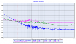
If someone was interested I attach the phase noise plots.
Each picture's title explains what has been measured.
I believe this thread is more appropriate to discuss the measurements.
Each picture's title explains what has been measured.
I believe this thread is more appropriate to discuss the measurements.
Attachments
-
 01 fifopi-mclk-crystek-cchd-957-24-576-mhz-phase-noise-png.png61.1 KB · Views: 676
 -
 09 fifopi_lrck-jpg.jpg136.9 KB · Views: 238
 -
 08 fifopi-lrck-rpi-crystek-driscollxo-att6db-png.png94.3 KB · Views: 193
 -
 07 fifopi-sck-rpi-crystek-driscollxo-att6db-png.png99.5 KB · Views: 211
 -
 06 rpi-fifopi-lrck-driscoll-22-5792-mhz-phase-noise-png.png108.3 KB · Views: 220
 -
 05 rpi-fifopi-sck-driscoll-22-5792-mhz-phase-noise-png.png113.1 KB · Views: 622
 -
 04 fifopi-mclk-crystek-24-576-_-driscoll-22-5792-mhz-phase-noise-png.png96.6 KB · Views: 617
 -
 03 rpi-fifopi-lrck-crystek-cchd-957-24-576-mhz-phase-noise-png.png102.8 KB · Views: 603
 -
 02 rpi-fifopi-sck-crystek-cchd-957-24-576-mhz-phase-noise-png.png106.5 KB · Views: 674
Could help to show all the good work made
Thank you Andrea,
Could it be possible to attach in a post as above the measurment captures from 1 Hz of the former 2017 Discroll with At-Cut & SC-CUT side to side with the new Discroll board please with these same crystal?
And the new Pierce AT-Cut as well to show how it performs side to side to the former's
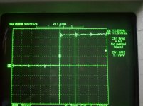
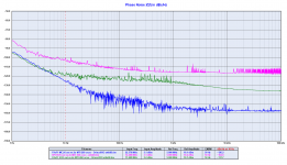
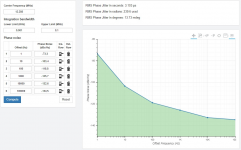
First picture: FifoPi SCK measured jitter is 2.7 ps
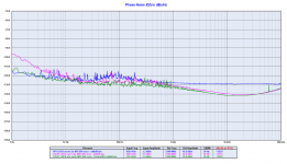
Second picture: FifoPi SCK calculated jitter from phase noise measurement is 3.1 ps
Measurement difference: 400 fs (3.1 - 2.7 ps)
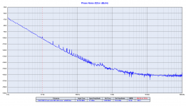
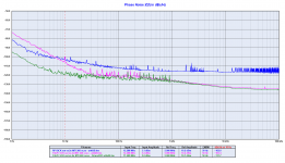
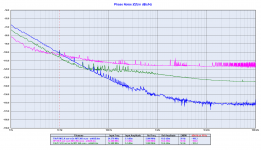
Third picture: FifoPi measured phase noise (used to calculate jitter), green curve drives PCM1794, PCM1704 and so on.
Crystek 24.576 MHz master clock noise floor is -160 dBc, FifoPi SCK 12.288 MHz noise floor is -130dBc, RPI SCK 12.288 MHz is -115 dBc
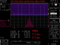
Fourth picture: FifoPi LRCK 192 kHz wave captured with the oscilloscope, there is crosstalk at SCK clock (12.288 MHz), this wave drives TDA1541A, AD1865, AD1862 and so on.
Crosstalk should be removed, the LRCK clock does not need the SCK to be superimposed.
Second picture: FifoPi SCK calculated jitter from phase noise measurement is 3.1 ps
Measurement difference: 400 fs (3.1 - 2.7 ps)
Third picture: FifoPi measured phase noise (used to calculate jitter), green curve drives PCM1794, PCM1704 and so on.
Crystek 24.576 MHz master clock noise floor is -160 dBc, FifoPi SCK 12.288 MHz noise floor is -130dBc, RPI SCK 12.288 MHz is -115 dBc
Fourth picture: FifoPi LRCK 192 kHz wave captured with the oscilloscope, there is crosstalk at SCK clock (12.288 MHz), this wave drives TDA1541A, AD1865, AD1862 and so on.
Crosstalk should be removed, the LRCK clock does not need the SCK to be superimposed.
Attachments


TDA1541a user
This is fascinating stuff. As a 1541a user it catches my interest. I use the FIFOpi driven by your SC cut @ 45mHz with Ian's I2StoPCM board. No question I saw a massive improvement when installing your clock over the NDK clock it replaced. Now I am curious to understand what is actually reaching the 1541a chip. I am really listening to the I2StoPCM device. It depends on MCLK to generate it's output. Good to know MCLK is faithful to the clock, but I suppose the sound quality ultimately depends on the jitter of the I2StoPCM device.
What would be interesting for the diehard 1541a crowd would be a FIFO that produces PCM output with all signals with jitter of your new 5mHz SC cut crystal. I know you are headed down a better path with SOTA DAC, but any advice you have for the 1541a users will be appreciated.
The best advice I can give is to generate the LRCK dividing directly the master clock outside of the FPGA with separate VCC and ground.
With 5/6 MHz master clock you can play 176/192 kHz.
With 5/6 MHz master clock you can play 176/192 kHz.
Good Advice
I have concluded that I am happy with redbook so a single 5mHz is sufficient when you are ready.
I have a pcb from Ryanj based on ecdesigns that would generate the LRCK. It at least eliminates one FPGA in the chain. Time to dust that one off and try it. Thanks
I have concluded that I am happy with redbook so a single 5mHz is sufficient when you are ready.
I have a pcb from Ryanj based on ecdesigns that would generate the LRCK. It at least eliminates one FPGA in the chain. Time to dust that one off and try it. Thanks
I guess I won't have a more opportune time to ask this question... TWTMC threads are too intimidating for a noob and I haven't gone through my Accusilicon level up phase yet.
I too am redbook only and looking at the 5mHz down the road. If I can successfully implement the Accusilicons, the ultimate next step would be a single 5mHz.
But I'm trying to keep a low footprint with LiFePO4Battery-UPS/RPi/FiFoPi/TransportPi, so I don''t want separate boards and wiring. The photos I've have seen in the TWTMC threads all seem to have separate boards and wiring which is a dealbreaker at this time. Is there a simple single 5mHz drop-in replacement solution without having wires dangle and powering a separate board?
If for example I can just remove the Accusilicons and drop-in a 5mHz in it's place without having to deal with external components outside the FiFoPi/TransportPi ecosystem. Thanks.
Last edited:
I'm sorry but the plug & play solution you are asking for is not available.
The reason is that there are physical limits, just the 5 MHz crystal is larger than the Accusilicon package.
I understand that the stacked solution is practical, but it's not the best audiophile way.
The Raspberry generats a lot of EMI/RFI so it should be kept as far as possible from the other devices.
No worries that there is no plug & play solution. It's targeted towards the best audiophile solution, not the most transportable solution.
I'll just try to adjust and build separate Fifo gear depending on transportable or stationery use.
So if one wanted to experiment with TWTMC and only into redbook, would the following two parts be enough to get started with a FiFoPi/TransportPi?
Crystals:
SC 5.6448 MHz 3rd overtone 15 73,00
Finished boards:
TWTMC-DRIXO-F New Driscoll XO (without crystal) 120,00
Cheers for taking time away from the technical side of things to answer an implementation question.
It's difficult for newcomers to explore what options are available so this is very helpful.
You are welcome, I'm happy to help if I can.
Yes, you need the parts you have mentioned, and a clean 12 to 18V power supply, batteries or low noise linear regulator.
Yes, you need the parts you have mentioned, and a clean 12 to 18V power supply, batteries or low noise linear regulator.
Looking forward to your LiFePO4 and Fifo products. It will be nice to have different options at different price and performance points. Unfortunately, I need optical out so your Fifo product may not work out for my case. I will need to stick with a Fifo product that can utilize the TransportPi or have an optical out.
Since I know which basic parts I need I may get in on GB last minute if adventurous. I want to get my feet wet first with the Accusilicon, so not in a rush. But a TWTMC is needed if I want to reach ultimate audio nirvana.
Since I know which basic parts I need I may get in on GB last minute if adventurous. I want to get my feet wet first with the Accusilicon, so not in a rush. But a TWTMC is needed if I want to reach ultimate audio nirvana.
For my preferences, yes. I plan to run only Chord DACs going forward, so I'm limited to optical, coax, and USB inputs. My preference for Chord DACs is glass optical input and redbook so I'm trying to stay on that course. I doubt these DAC input options will change in the next 5 years, so I will be limited.
My plan is just to experiment with clock-rolling Squeezebox Music Streamers to see if they make a difference. Then possibly experiment with LiFePO4 power supplies as my preference is battery-power.
If I knew how to put together a TWTMC from the beginning, I would of skipped the Accusilicon step altogether. Unfortunately, Accusilicon is already a sunk cost so I'll focus on that build for this year.
Eventually, depending on timing I would like to see how the TWTMC plays out in the system by next summer.
For my preferences, yes. I plan to run only Chord DACs going forward, so I'm limited to optical, coax, and USB inputs. My preference for Chord DACs is glass optical input and redbook so I'm trying to stay on that course. I doubt these DAC input options will change in the next 5 years, so I will be limited.
My plan is just to experiment with clock-rolling Squeezebox Music Streamers to see if they make a difference. Then possibly experiment with LiFePO4 power supplies as my preference is battery-power.
If I knew how to put together a TWTMC from the beginning, I would of skipped the Accusilicon step altogether. Unfortunately, Accusilicon is already a sunk cost so I'll focus on that build for this year.
Eventually, depending on timing I would like to see how the TWTMC plays out in the system by next summer.
Not sure whether optical out from FIFO setup makes most sense. Anectodially I read that optical transport adds substantial jitter due to light reflections within the cable. Which could mean even though you get a perfectly timed signal from FIFO, the outcome might have substantial jitter on the other side of the cable.
Might make sense to dig deeper on this topic.
Just my 2 cents.
Can a Chord Dac be slaved ? I'm not sure ! And it's fgpa inside which is oversampling at max !
You are welcome, I'm happy to help if I can.
Yes, you need the parts you have mentioned, and a clean 12 to 18V power supply, batteries or low noise linear regulator.
Andrea what 12-18V power supply you use.
Not sure whether optical out from FIFO setup makes most sense. Anectodially I read that optical transport adds substantial jitter due to light reflections within the cable. Which could mean even though you get a perfectly timed signal from FIFO, the outcome might have substantial jitter on the other side of the cable.
Might make sense to dig deeper on this topic.
Just my 2 cents.
For my first experiment with RPi/HiFiBerry Digi+ Pro it works pretty well. I enjoy the PrAT with the built-in clocks. I could not get this PrAT with any other inputs. That leads me to want to try the next step which is the FiFoPi w/ Accusilicon.
The Chord DACs actually re-clock internally to eliminate jitter, so this is mostly an experiment to check if clocks make a difference since I experienced improved PrAT with the HiFiBerry. I noticed other high-end streamers use Crystek clocks and Chord users notice improvements when they add these high-end streamers with clocks into the mix. Even something like Uptone devices use Crystek for their builds.
So this is mainly an experiment. It may even be redundant since it all may re-clock in the end, but I and others notice improvements so want to see how far this goes. I hope it pays off but understand the risks if it doesn't work out. If I can squeeze out just slightly better PrAT, it will be worth the experiment in the end.
I don't really have much choice but to stick with optical as it's a preference and eliminates RFI.
I like to eventually have 3 music streamers to experiment:
A) RPi/HiFiBerry Digi+ Pro
B) RPi/FiFoPi/TransportPi/Accusilicon
C) RPi/FiFo*/Opt Out/5 MHz Crystal
Last edited:
- Home
- Source & Line
- Digital Line Level
- Asynchronous I2S FIFO project, an ultimate weapon to fight the jitter