Fix 384KHz issue(1): Understanding I2S timing requirement from I2S BUS standard
I did some test and confirmed that one kind of XMOS USB has issue with FIFO running at 384KHz. It was OK if feeding signals directly into FIFO, but had noise over music if signals went through an isolator or the backdoor of the S/PDIF board, 352KHz also showed unstable under same condition.
At beginning, I was suspecting the re-clocking, the impedance of PCB trace or the speed of the on board NVE isolator. But finally, it was approved none of them was the key reason cause that problem.
So I did more test on last weekend to work out with this issue and trying to find out both the reason and the solution.
Again, I'm not a qualified testing lab. What I’m doing is just to address issues with my FIFO project. The testing result will only apply to my project and doesn't mean anything to any other product. That USB that has issue with my FIFO may don’t have any problem at all with other product.
Please follow my story if you are interested in my research. I’m gonna begin with I2S BUS standard.
Two attached pictures were picked up from I2S BUS standard.
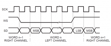
1. The first waveform indicates what I2S output signals should be.
It tells us that SD(DATA) and WS(LRCK) should be changed at the moment of falling edge of SCK and will be registered into I2S receiver at the raising edge of SCK.
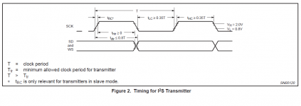
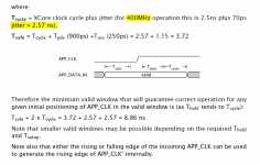
2. The second waveform tells us the basic requirement of I2S timing.
Please note that we usually don’t have problem with all other conditions besides of this one, which is:
Tdtr<0.8T, it means Tsu (setup time) > 0.2T
When running at 384KHz with SCK=64Fs, Fsck=24.576MHz, so, T=40.69ns
In this case, the setup time condition becomes Tsu > 8.14ns
The second condition has to be met, otherwise it will put the receiver in much higher risk of getting wrong data.
The setup time is the data stable time before the moment of effective edge of clock comming, please see wikipedia for details:
Flip-flop (electronics) - Wikipedia, the free encyclopedia
I’m gonna do some test one by one on all USBs with my LeCroy to see what will be discovered from monitoring their output signals. Hopefully I can address the 384KHz issue.
Ian
I did some test and confirmed that one kind of XMOS USB has issue with FIFO running at 384KHz. It was OK if feeding signals directly into FIFO, but had noise over music if signals went through an isolator or the backdoor of the S/PDIF board, 352KHz also showed unstable under same condition.
At beginning, I was suspecting the re-clocking, the impedance of PCB trace or the speed of the on board NVE isolator. But finally, it was approved none of them was the key reason cause that problem.
So I did more test on last weekend to work out with this issue and trying to find out both the reason and the solution.
Again, I'm not a qualified testing lab. What I’m doing is just to address issues with my FIFO project. The testing result will only apply to my project and doesn't mean anything to any other product. That USB that has issue with my FIFO may don’t have any problem at all with other product.
Please follow my story if you are interested in my research. I’m gonna begin with I2S BUS standard.
Two attached pictures were picked up from I2S BUS standard.
1. The first waveform indicates what I2S output signals should be.
It tells us that SD(DATA) and WS(LRCK) should be changed at the moment of falling edge of SCK and will be registered into I2S receiver at the raising edge of SCK.
2. The second waveform tells us the basic requirement of I2S timing.
Please note that we usually don’t have problem with all other conditions besides of this one, which is:
Tdtr<0.8T, it means Tsu (setup time) > 0.2T
When running at 384KHz with SCK=64Fs, Fsck=24.576MHz, so, T=40.69ns
In this case, the setup time condition becomes Tsu > 8.14ns
The second condition has to be met, otherwise it will put the receiver in much higher risk of getting wrong data.
The setup time is the data stable time before the moment of effective edge of clock comming, please see wikipedia for details:
Flip-flop (electronics) - Wikipedia, the free encyclopedia
I’m gonna do some test one by one on all USBs with my LeCroy to see what will be discovered from monitoring their output signals. Hopefully I can address the 384KHz issue.
Ian
Attachments
Last edited:
Thanks, Ian.
I look forward to trying the WaveIO direct to FIFO to see if my results can mirror yours.
Regards,
Shane
I look forward to trying the WaveIO direct to FIFO to see if my results can mirror yours.
Regards,
Shane
384Khz and WaveIO/Fifo
Good work, so far Ian. I am very curious.
In the mean time I tried the OttoII mux, from TP, but the same problem as you discribe! WaveIO fed straight in to the Fifo: everything is fine, all other routes have problems with >192KHz.
The trick with the OttoII switch did not give the solution either. 352 lightly disturbed (now and than), 384 heavily disturbed!
So after all it looks like , in this setup, another USB interface will be the curing step, (sniff), or you come up with a solution, but do not feel pressed, you have done enough already,
Regards,
Ed
I did some test and confirmed that one kind of XMOS USB has issue with FIFO running at 384KHz. It was OK if feeding signals directly into FIFO, but had noise over music if signals went through an isolator or the backdoor of the S/PDIF board, 352KHz also showed unstable under same condition.
At beginning, I was suspecting the re-clocking, the impedance of PCB trace or the speed of the on board NVE isolator. But finally, it was approved none of them was the key reason cause that problem.
So I did more test on last weekend to work out with this issue and trying to find out both the reason and the solution.
Again, I'm not a qualified testing lab. What I’m doing is just to address issues with my FIFO project. The testing result will only apply to my project and doesn't mean anything to any other product. That USB that has issue with my FIFO may don’t have any problem at all with other product.
Please follow my story if you are interested in my research. I’m gonna begin with I2S BUS standard.
Two attached pictures were picked up from I2S BUS standard.
1. The first waveform indicates what I2S output signals should be.
It tells us that SD(DATA) and WS(LRCK) should be changed at the moment of falling edge of SCK and will be registered into I2S receiver at the raising edge of SCK.
2. The second waveform tells us the basic requirement of I2S timing.
Please note that we usually don’t have problem with all other conditions besides of this one, which is:
Tdtr<0.8T, it means Tsu (setup time) > 0.2T
When running at 384KHz with SCK=64Fs, Fsck=24.576MHz, so, T=40.69ns
In this case, the setup time condition becomes Tsu > 8.14ns
The second condition has to be met, otherwise it will put the receiver in much higher risk of getting wrong data.
The setup time is the data stable time before the moment of effective edge of clock comming, please see wikipedia for details:
Flip-flop (electronics) - Wikipedia, the free encyclopedia
I’m gonna do some test one by one on all USBs with my LeCroy to see what will be discovered from monitoring their output signals. Hopefully I can address the 384KHz issue.
Ian
Good work, so far Ian. I am very curious.
In the mean time I tried the OttoII mux, from TP, but the same problem as you discribe! WaveIO fed straight in to the Fifo: everything is fine, all other routes have problems with >192KHz.
The trick with the OttoII switch did not give the solution either. 352 lightly disturbed (now and than), 384 heavily disturbed!
So after all it looks like , in this setup, another USB interface will be the curing step, (sniff), or you come up with a solution, but do not feel pressed, you have done enough already,
Regards,
Ed
Last edited:
Fix 384KHz issue(2): New version XMOS USB output timing test (in BGA package 48M)
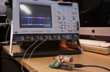
Testing Condition
Playing status: Running 384KHz music properly
Test equipment: LeCroy LC584AXL 1GHz Oscilloscope
Sample Rate: 4GS/s
Total sample time: 20 seconds
Time Base: 10ns/div & 2ns/div
Input: 1X 50ohm coaxial cable
I2S frequency: 384 KHz
With isolator: Yes
Music source: iMac - OS X Mavericks – iTunes – USB - isolator
System Configuration: FIFO - Dual XO clock board (45/49MHz) - PCM board - TDA1541A DAC (simultaneous mode)
Numbers from waveform
SCK(BCK) jitter (Cycle to Cycle): around 2ns, systematic
SD(DATA),WS(LRCK) skew ( raising or falling edge, reference to BCK): around 2ns
SD(DATA),WS(LRCK) setup time Tsu: 19.5 ns
Ian
Attachments

Last edited:
Isolator
Hi Ian,
Forgot to ask.
What is the difference between this 'universal' isolator and the 2.5 I got fron you in one of the GB's?
Regards,
Ed
Hi Ed,
I have already order the new generation xome usb, I'll put some update once I received it. Hopefully the new BGA version of XMOS doesn't have this issue.
The universal I2S/DSD isloator was here:
http://www.diyaudio.com/forums/digi...mate-weapon-fight-jitter-213.html#post3329364
I still have some prototype PCB. I can give you one or two if you want.
Regards,
Ian
Hi Ian,
Forgot to ask.
What is the difference between this 'universal' isolator and the 2.5 I got fron you in one of the GB's?
Regards,
Ed
Hi Ian,
Forgot to ask.
What is the difference between this 'universal' isolator and the 2.5 I got fron you in one of the GB's?
Regards,
Ed
Hi Ed,
The universal isolator is for isolating standard I2S/DSD signals from source. It works for most I2S/DSD sources such as USB music interfaces, but the clock board.
The GB isloator was specially designed to isolate clock board from FIFO. Thay are working for different applications.
Regards,
Ian
isolator
Thanks for the explanation, Ian.
What do you suggest as best place for isolating:
a) Between USB and Fifo
or
b) Between Fifo and clockboard. After removing L11 (on dual clock board) there is no real need for isolating there.
Regards, Ed
Hi Ed,
The universal isolator is for isolating standard I2S/DSD signals from source. It works for most I2S/DSD sources such as USB music interfaces, but the clock board.
The GB isloator was specially designed to isolate clock board from FIFO. Thay are working for different applications.
Regards,
Ian
Thanks for the explanation, Ian.
What do you suggest as best place for isolating:
a) Between USB and Fifo
or
b) Between Fifo and clockboard. After removing L11 (on dual clock board) there is no real need for isolating there.
Regards, Ed
Last edited:
Thanks for the explanation, Ian.
What do you suggest as best place for isolating:
a) Between USB and Fifo
or
b) Between Fifo and clockboard. After removing L11 (on dual clock board) there is no real need for isolating there.
Regards, Ed
Hi Ed,
If you use only one isolator, the one between FIFO and clock board is the best for sure.
But I would suggest you using both if it is possible, because PC ground is always negative to audio system.
Ian
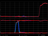
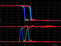
Fix 384KHz issue(3): Combo384 USB output timing test
Testing Condition
Playing status: Running 384KHz music properly
Test equipment: LeCroy LC584AXL 1GHz Oscilloscope
Sample Rate: 4GS/s
Total sample time: 20 seconds
Time Base: 10ns/div & 2ns/div
Input: 1X 50ohm coaxial cable
I2S frequency: 384 KHz
With isolator: Yes, universal I2S/DSD isolator
Music source: iMac - OS X Mavericks – iTunes – USB - isolator
System Configuration: FIFO - Dual XO clock board (45/49MHz) - PCM board - TDA1541A DAC (simultaneous mode)
Numbers from waveforms
SCK(BCK) jitter (Cycle to Cycle): Couldn’t be measured with accurate under current setup of oscilloscope
SD(DATA),WS(LRCK) skew ( raising or falling edge, reference to BCK): around 200ps
SD(DATA),WS(LRCK) setup time Tsu: 9.1 ns
Ian
Attachments
USB-I2S findings
Hi Ian,
Seems that the Amanero is doing a better job here?
Ed
Testing Condition
SCK(BCK) jitter (Cycle to Cycle): Couldn’t be measured with accurate under current setup of oscilloscope
SD(DATA),WS(LRCK) skew ( raising or falling edge, reference to BCK): around 200ps
SD(DATA),WS(LRCK) setup time Tsu: 9.1 ns
Ian
Hi Ian,
Seems that the Amanero is doing a better job here?
Ed
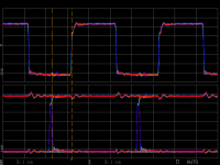
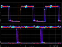
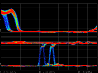
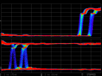
Fix 384KHz issue(4):Old version XMOS USB output timing test (TQFP package 13M clock)
Testing Condition
Playing status: Running 384KHz with noise over music, 352KHz is OK in most of time but still not 100% stable. 192KHz or lower no any problem.
Test equipment: LeCroy LC584AXL 1GHz Oscilloscope
Sample Rate: 4GS/s
Total sample time: 20 seconds
Time Base: 10ns/div & 2ns/div
Input: 1X 50ohm coaxial cable
I2S frequency: 384 KHz
With isolator: Yes, internal
Music source: iMac - OS X Mavericks – iTunes – USB - isolator
System Configuration: FIFO - Dual XO clock board (45/49MHz) - PCM board - TDA1541A DAC (simultaneous mode)
Numbers from waveforms
SCK(BCK) jitter (Cycle to Cycle): around 2.08ns, systematic
SD(DATA),WS(LRCK) skew ( raising or falling edge, reference to BCK): around 2.08ns, systematic
SD(DATA),WS(LRCK) setup time Tsu: 3.4 ns
Ian
Attachments

Fix 384KHz issue(5): Analyzing and finding of the reason of the issue
Testing results analysis:
1. New version XMOS USB
LRCK and SD were changing exactly at the moment of falling edge of SCK with very good Tsu close to 20ns
However, Jitter and skew were very big up to around 2ns and appeared to be systematic mainly. It was because XMOS generates I2S signals by software and It seems that this new XOMS CPU was running at 500MHz (2ns system clock cycle).
2. Combo384 USB
Jitter and skew were within reasonable range and couldn’t be measured by oscilloscope with accurate under current setting, no systematic jitter and skew found from output clock and other signals.
LRCK and SD were not changing at moment of falling edge of SCK, but with some delay, however the 9.1ns Tsu was still within tolerance range of I2S BUS specification which should be greater than 8.14ns.
3. Old version XMOS USB
Jitter and skew were very big up to around 2.08 ns and appeared to be systematic. It was because I2S signals were generated by software. But it seems this old version XOMS CPU was also running at around 500MHz internal system clock rather than 400MHz from the spec. I suspect the new FW with 384KHz support running the CPU at higher speed than before.
LRCK and SD were not changing at moment of falling edge of SCK, both of them have very big delay, which lead to Tsu goes less than 3.4ns. This 3.4ns Tsu was already out of (less than) the tolerance range required by I2S BUS specification which should be greater than 8.14ns.
Conclusions:
I’m not the first one who found XMOS USB has 2-2.5ns systematic jitter over I2S output signals, I just confirmed it again by my testing. XOMS has already described this well known issue very clear in the document “XS1 Port I/O Timing Application Note”. However, the output jitter is really not the main reason of the 384KHz problem, though it could make the case even worse in some degree. That explains why the new version XMOS USB was OK with 384KHz.
Setup time Tsu out of (not enough) the tolerance range of I2S BUS specification was the main reason of old XMOS 384KHz issue. It puts the I2S receiver of FIFO at very dangerous situation of getting wrong data without enough setup time. FIFO needs input signals have at least 5ns safe setup time Tsu to ensure 100% error free. Though it’s already in a bigger tolerance range than the I2S BUS specification, but still cannot cover the case of the old XMOS running 384KHz with isolator or back door. That also explains why feeding 384 KHz into FIFO without isolator was OK for sometimes, but with an isolator or going through backdoor of S/PDIF board was noisy. Both of the isolator and the buffer of the backdoor introduce additive skew which makes Tsu even worse.
The next, I’ll try some possible solutions according to this conclusion to see if I can approve something. Hopefully I can finally fix this 384KHz problem.
Ian
Attachments
Fix 384KHz issue(6): Possible solutions to fix the issue
1. FW solution
Firmware solution could be the best solution. Since all I2S signals were generated by firmware, just make LRCK and SD updating the logic level at same moment of falling edge of SCK, all problems can be solved. If LRCK and SD were generated according to SCK (because I saw there was a delay), then just simply generate a new SCK together with LRCK and SD, and make it as output. It seems the new XMOS USB doing it this way (please see the waveform), so I think it should be achievable.
2. External re-clock board
A flip-flop logic or FPGA based external re-clock board can solve this problem for sure. But it will increase system complexity.
3. Make FIFO working with small Tsu
Make FIFO tolerance with Tsu less than 3ns is possible and achievable. However I have to evaluate if there is any negative effect of working with non-standard I2S signals.
4. Delay SCK
Since the reason of the problem was Tsu not enough (too short) , so adding a 5-10ns delay to SCK could make Tsu meeting the requirement of I2S BUS specification at 384KHz which has to be 8.14ns or greater.
To implement this solution could be very easy, we just need finding a buffer with suitable 5-10ns delay, and insert into the SCK chain, either before or after the isolater. The only thing is that we have to mod the old XMOS PCB. I’ll try this solution the next. If the concept is promising, it will prove my conclusions.
Ian
Last edited:
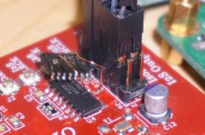
Fix 384KHz issue(7): Implement solution 4 - delay SCK after isolator
Though the XMOS USB has around 2ns systematic jitter and skew on output signals, but that’s not the key reason of the noise issue of playing 384Khz. Actually, with FIFO included in our system, we don’t care about that amount of jitter.
According to my testing result, the main reason of old version XMOS 384KHz problem was the too short setup time Tsu. If it is true, then making the Tsu longer will solve the problem.
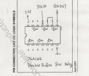
There are many ways to make set up time Tsu longer. One of the ideas is to insert a buffer within SCK chain. According to what I understand from I2S BUS specification, the sweet Tdtr range could be from 0.5T to 0.8T, in this case, if I can make SCK with 5-10ns delay we can meet this range.
I just happened to have a 74AC04, which can be 8ns delay with double buffers. So, for the first implement, I cut the SCK trace after isolator on the XMOS PCB and insert the double buffered 74AC04. So, guess what? I made it! It starts to play 384 KHZ music wonderful without any problem, the noise was gone, even with the on-board isolator! The setup time Tsu was measured as 9.3ns now.
This implement confirmed that my conclusion is correct. But you may have noticed that the waveform look not that nice, that was because AC04 is not a low noise chip and two buffers introduced quite a few amount of additive jitter as well.
Ian
Though the XMOS USB has around 2ns systematic jitter and skew on output signals, but that’s not the key reason of the noise issue of playing 384Khz. Actually, with FIFO included in our system, we don’t care about that amount of jitter.
According to my testing result, the main reason of old version XMOS 384KHz problem was the too short setup time Tsu. If it is true, then making the Tsu longer will solve the problem.
There are many ways to make set up time Tsu longer. One of the ideas is to insert a buffer within SCK chain. According to what I understand from I2S BUS specification, the sweet Tdtr range could be from 0.5T to 0.8T, in this case, if I can make SCK with 5-10ns delay we can meet this range.
I just happened to have a 74AC04, which can be 8ns delay with double buffers. So, for the first implement, I cut the SCK trace after isolator on the XMOS PCB and insert the double buffered 74AC04. So, guess what? I made it! It starts to play 384 KHZ music wonderful without any problem, the noise was gone, even with the on-board isolator! The setup time Tsu was measured as 9.3ns now.
This implement confirmed that my conclusion is correct. But you may have noticed that the waveform look not that nice, that was because AC04 is not a low noise chip and two buffers introduced quite a few amount of additive jitter as well.
Ian
Attachments
Last edited:
Fix 384KHz issue(8): Implement solution 4 - delay SCK before isolator
The second implement, I cut the SCK trace before isolator (between the resistor arrays) on the XMOS PCB and insert the double buffered 74AC04 in between. No doubt, it works at 384 KHZ without problem too, even with the on-board isolator!
With this implement, the waveform looks better, however the additive jitter was even worse.
Though I confirmed insert delay buffer (solution 4, either before or after the isolater) can fix the old XMOS 384KHz issue, but it’s not the best solution. Because not only have to mod the XMOS PCB, but also introducing new additive jitter.
I heard Lorien is gonna upgrade the FW to solve this issue, if so, that would be solution No.1. So please just hold for now, maybe we don’t need doing anything to the hardware.
Ian
Attachments
Hi all,
if anyone was interested in the custom Laptech crystal
http://www.diyaudio.com/forums/grou...hronous-i2s-s-pdif-fifo-kit-group-buy-70.html
please add your name in the wish list at
http://www.diyaudio.com/forums/digital-line-level/203511-any-good-tda1541a-dac-kit-96.html
The minimum orderable quantity from Laptech is 5 pcs for each frequency.
When that quantity will be reached I ask Laptech for a quote.
Andrea
As promised, the list of interest is started.
http://www.diyaudio.com/forums/digi...-jitter-crystal-oscillator-4.html#post4057057
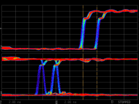
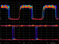
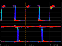
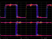
Fix 384KHz issue(9): Implement solution 1 – Issue fixed by new firmware
I upgraded my WaveIO USB with Lorien’s new sent FW last weekend and confirmed it works. The new FW has 17ns setup time on I2S signals rather than the previous 3.4ns. As well, LRCK and SD are changing exactly at the moment of falling edge of SCK now which meets the requirement of I2S BUS specification. The 384KHz issue was fixed, which just as I said, the solution1 is the best solution.
It works very well, even together with the on-board isolator and the I2S backdoor of the S/PDIF interface board. The music plays very nice at 384KHz, no any noise at all.
The attached screen shots are current measured waveform of WAVEIO USB running at 384KHz with new FW.
Please refer to the old waveform here to find out what’s the difference:
http://www.diyaudio.com/forums/digi...mate-weapon-fight-jitter-340.html#post4038295
Ian
Attachments
Last edited:
- Home
- Source & Line
- Digital Line Level
- Asynchronous I2S FIFO project, an ultimate weapon to fight the jitter