I found those at DALBANI
Cob 2pf.... in this case maybe I can not use such a low Cdom
Cob 2pf.... in this case maybe I can not use such a low Cdom
Last edited:
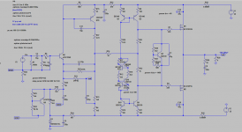
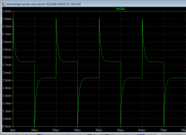
I am getting really nice spikes in the input transistor collector using 2SA1407 running at 11mA.....
Please verify my 2SA1407 model and I would also appreciate stability confirmation (Frans 🙂)
This is looking really promising.
Please verify my 2SA1407 model and I would also appreciate stability confirmation (Frans 🙂)
This is looking really promising.
Attachments
LT Spice model:
.MODEL 2SA1407 PNP (IS=20.9E-15 BF=95 NF=1 BR=0.5355 NR=1 ISE=0 NE=1.0 ISC=0
+ NC=1.0 VAF=80 VAR=20 IKF=0.3 IKR=0.5 RB=5 RBM=5 IRB=3.6308E-3 RE=2 RC=5 CJE=8.25E-12
+ VJE=0.7 MJE=0.3658 FC=0.5 CJC=7.71E-12 VJC=0.5 MJC=0.3964 XCJC=0.5 XTB=2.3 EG=1.11 XTI=3.0 )
.MODEL 2SA1407 PNP (IS=20.9E-15 BF=95 NF=1 BR=0.5355 NR=1 ISE=0 NE=1.0 ISC=0
+ NC=1.0 VAF=80 VAR=20 IKF=0.3 IKR=0.5 RB=5 RBM=5 IRB=3.6308E-3 RE=2 RC=5 CJE=8.25E-12
+ VJE=0.7 MJE=0.3658 FC=0.5 CJC=7.71E-12 VJC=0.5 MJC=0.3964 XCJC=0.5 XTB=2.3 EG=1.11 XTI=3.0 )
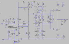
Due to the high cost and dubious spice model the 2SA1407 is off.
I Found the 2SA1381 that I can get from reichelt and included in the Cordell lib.
So here is my last sim that looks ok.
I will now rest and wait for your approval and fine-tuning if possible 🙂
I Found the 2SA1381 that I can get from reichelt and included in the Cordell lib.
So here is my last sim that looks ok.
I will now rest and wait for your approval and fine-tuning if possible 🙂
Attachments
I have been simulating with this last version and I can not see instabilities using low Cdom values but I am not sure..... Looking forward for some input from you guys 🙂
I would just build it.
You can adjust the square wave later with capacitive load.
Say 8 Ohm in parallel with 0.1uF.
When you use a dynamic speaker and your cable is not super high capacitance the stability will not be taxed anyway.
A dynamic speaker behaves more like an inductor at higher frequencies.
To make an unstable amp under this conditions need really high incompetence.
When you use an electrostatic speaker you need a zobel anyway.
What do you mean ?
PS: My build has a zobel in the output....
I would just build it.
You can adjust the square wave later with capacitive load.
Say 8 Ohm in parallel with 0.1uF.
When you use a dynamic speaker and your cable is not super high capacitance the stability will not be taxed anyway.
A dynamic speaker behaves more like an inductor at higher frequencies.
To make an unstable amp under this conditions need really high incompetence.
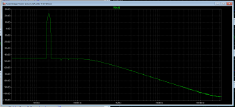
So this 0.1uF would be the worst case cable capacitance right ?
In simulation, this cap produces a nasty rise in gain from 27dB to 32dB at 1.9MHz.... this peaking might indicate instability.
Placing a 50uH in series with the 8ohm load does not affect stability.
I will build it and trim Cdom latter.
Member
Joined 2009
Paid Member
For simulating phase margin you can add a little capacitance in parallel with the load, say 1nF, which will give you some idea as to how sensitive the amp is to nasty cables.
I'd add a resistor in series with R24 so that the adjustment of dc-offset is easier, less sensitive.
I'm unfamiliar with the output FETs you've chosen. In the final design it might be prudent to allow for some footprints on the pcb for additional SMT components to tame any vhf instability that FETs can exhibit. By this I mean add a gate-drain zobel (see my TGM8 schematic).
You have no output source resistors - is this OK ?
On a completely crazy note - I wonder if you could throw out the current mirrors and use double bootstrap for the Vbe multiplier to give more voltage headroom for those FETs ?
On a completely crazy note - I wonder if you could throw out the current mirrors and use double bootstrap for the Vbe multiplier to give more voltage headroom for those FETs ?
Gareth, makes a lot of sense to me, however, I would go even more crazy and try putting the Vbe multiplier in series with VAS collector, driving the FETs directly fron VAS 😉
With the laterals that gives sense too, but I would not alter the concept too much, this is why I stuck with the mirror drive, removing it would render a JHL type circuit. with care it would sound very good. theres no doubt that the mirror floating CCS does hold some slack, this is the reason why i suggested the improved mirrors.
Gareth, makes a lot of sense to me, however, I would go even more crazy and try putting the Vbe multiplier in series with VAS collector, driving the FETs directly fron VAS 😉
Off course but that would mean I would be building the TGM8 instead.
Remember the initial idea was to develop the Nobrainer loosing it's opamp input stage... that is why I searched for Gareth's singleton input.
Anyway it works really well... just needs some finetunning to improve it's treble.
For simulating phase margin you can add a little capacitance in parallel with the load, say 1nF, which will give you some idea as to how sensitive the amp is to nasty cables.
I'd add a resistor in series with R24 so that the adjustment of dc-offset is easier, less sensitive.
I'm unfamiliar with the output FETs you've chosen. In the final design it might be prudent to allow for some footprints on the pcb for additional SMT components to tame any vhf instability that FETs can exhibit. By this I mean add a gate-drain zobel (see my TGM8 schematic).
You have no output source resistors - is this OK ?
On a completely crazy note - I wonder if you could throw out the current mirrors and use double bootstrap for the Vbe multiplier to give more voltage headroom for those FETs ?
It seems quite sensitive to capacitive loads .... will mod it soon and verify in reality.
Did not detect any nasties with the scope so I believe it is really stable without the zobel from gate to drain.
I get lower distortion without the source resistors and I believe they are not needed with this type of laterals as long as they are not paralleled.
Anyway this is Miibs output stage 🙂 So I'm cool
- Home
- Amplifiers
- Solid State
- Assemblage Power Amp