No, Kean, you are dead right, on all scores.
BUT, I wanted to have a highish input impedance to accommodate a passive tone control. So now that we've moved to an opamp based tone control with low Zout, then we could in fact reduce all fb impedances and thereby improve the phase lead issues.
However, a 5pF/15pF cap is easy to get, layout is not too difficult, and while distortion is higher with a higher impedance network, the question is by how much, and what profile?
If it's low order, then I would argue it's not important, but if it's an increase in H5/H7/H9 I would be most concerned and your stand would be totally vindicated.
Tone control is next.....
Cheers,
Hugh
Anyways, I would like to ask a small OT question that should be quick to answer.
Is there anything wrong with increasing the PL cap Hugh mentions to say, 56pF? I haven't seen any problems in my simulations.
EDIT: Hugh, I only meant the feedback network, not the input network. Just decrease the resistors on the feedback side of the LTP. And IIRC, there was a decrease in higher order distortions. I will try to dig up the thread.
- keantoken
Last edited:
In the simulator, this mod has had different affects on different amplifiers, presumably because the base current of the LTP transistors is the parasitic factor we are compensating for. I'm simming with the HAKSA to see what affect it has.
Here is the thread I mentioned:
http://www.diyaudio.com/forums/solid-state/145652-tgm2-amplifier-2.html#post1860642
If your computer is slow, wait for it to bring you to the specific post I made.
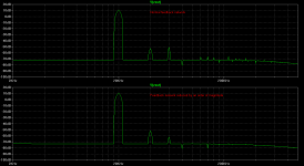
Okay, I have attached the simulation results. This worries me because I didn't expect it to be so significant! Whenever I get too successful on the simulator I ask others to verify my results, which is why I've also attached my simulation file with models included. The mod probably works well here because of the low OLG of the amp, which makes the base current of the LTP transistors larger (not to mention the non-CCS LTP loading).
This simulation was taken at 2V input, 20KHz. Something needing mentioning is that the feedback cap also has to be increased by a factor of 10.
- keantoken
Here is the thread I mentioned:
http://www.diyaudio.com/forums/solid-state/145652-tgm2-amplifier-2.html#post1860642
If your computer is slow, wait for it to bring you to the specific post I made.
Okay, I have attached the simulation results. This worries me because I didn't expect it to be so significant! Whenever I get too successful on the simulator I ask others to verify my results, which is why I've also attached my simulation file with models included. The mod probably works well here because of the low OLG of the amp, which makes the base current of the LTP transistors larger (not to mention the non-CCS LTP loading).
This simulation was taken at 2V input, 20KHz. Something needing mentioning is that the feedback cap also has to be increased by a factor of 10.
- keantoken
Attachments
Last edited:
Good point, although I don't remember Doug mentioning this specific tweak. My impression is that this amp was blameless to start with.
(and if you're referring to the PL cap, it's the phase lead cap that I want to increase. To my knowledge a large PL cap is not typical of Blameless amplifiers, while an enormous Cdom is.)
- keantoken
(and if you're referring to the PL cap, it's the phase lead cap that I want to increase. To my knowledge a large PL cap is not typical of Blameless amplifiers, while an enormous Cdom is.)
- keantoken
Aspen Headphone amp
keantoken
I was referring to your sim results.Those findings don't really surprise me, as many modern amps have much lower FB resistor values.
Regards
SandyK
keantoken
I was referring to your sim results.Those findings don't really surprise me, as many modern amps have much lower FB resistor values.
Regards
SandyK
Kean,
The impedances of the fb and input networks should match, so that there are identical voltage drops across fb and input bias resistors. This guarantees identical offset to ground, that is, 0mV.
Your simulation reveals low H3, H5, H7, etc artefacts. This is very useful, and I like it. I strive to reduce these, and ideally, to have monotonically decreasing artefacts if at all possible, generally only seen with SE circuits.
Hugh
I see, so I'm certainly not the first to "catch on".
Well Hugh, it is up to you whether we decrease the feedback resistors in light of this. As you said, there will be a little offset. This can be easily dealt with if we couple the opamp to the headphone amp with a long time constant, so that it acts as a DC servo as well as a tone control (I'm sure this can be done).
- keantoken
Last edited:
No, Kean, you are dead right, on all scores.
BUT, I wanted to have a highish input impedance to accommodate a passive tone control. So now that we've moved to an opamp based tone control with low Zout, then we could in fact reduce all fb impedances and thereby improve the phase lead issues.
Tone control is next.....
Cheers,
Hugh
Hello Hugh
Is it because of the db loss of passive tone control that you go for an opamp based tone control ?
Thank
Bye
Gaetan
Member
Joined 2009
Paid Member
IF the tone control circuit goes 'active' them I'm with KT on this, reducing the fb network resistances is a proven benefit in terms of distortion. I suspect that the faster fb network helps with higher order harmonics and doesn't 'spoil' the AKSA sound.
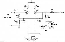
Douglas Self uses low value resistances in both FB and input for the reason Hugh stated, then bootstraps the input to the feedback point to increase input impedance.
SandyK
ref. Audio Power Amplifiers-D.Self vol.3 P.86
SandyK
ref. Audio Power Amplifiers-D.Self vol.3 P.86
Douglas Self uses low value resistances in both FB and input for the reason Hugh stated, then bootstraps the input to the feedback point to increase input impedance.
SandyK
ref. Audio Power Amplifiers-D.Self vol.3 P.86
Hello
You mean this one, have you try it in a amp ?
Can be interesting to try it in the Haksa amp.
Thank
Bye
Gaetan
Attachments
Last edited:
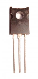
anybody got any pics of known good original 2SC3423 transistors? i got some recently that i'm not sure about ...
thx,
mlloyd1
thx,
mlloyd1
hugh:
thanks! what i have looks exactly like what you showed. i can sleep in peace now. see you guys later ...
mlloyd1
thanks! what i have looks exactly like what you showed. i can sleep in peace now. see you guys later ...
mlloyd1
Michael,
My pleasure. The contrast/resolution is not wonderful, but you can discern the font used, which is usually the giveaway.
Gaetan,
Yes, indeed, I found that achieving the required flat response was almost impossible without incorporating an opamp, and furthermore when Paul B. showed me a way to non-phase invert, it revealed that the opamp was very effective at reducing phase shifts, which create issues with passive Baxandall circuits.
We could have simply increased the gain of the HP amp to accommodate the losses of the tone control, but the phase anomalies would still have been there, and the opamp solution seemed the best. I would like to use a single ended solution, but it should be possible to achieve that with an opamp anyway by stringing a resistor from one rail to the output.
Gareth,
The AKSA has a very high impedance network, 47K/2K2, and yet has that magic sound much reported here and elsewhere. I'm not too sure it's necessary, and I suspect that a high impedance fb network loads up at high amplitude and might subtly change the output impedance of the amp, since the AKSA has an output which rises with loading, to a certain point.
The next move is to publish the tone control, something I hope to do tomorrow after Paul and I have had a chat about it.
Cheers,
Hugh
Gaetan,
Yes, indeed, I found that achieving the required flat response was almost impossible without incorporating an opamp, and furthermore when Paul B. showed me a way to non-phase invert, it revealed that the opamp was very effective at reducing phase shifts, which create issues with passive Baxandall circuits.
We could have simply increased the gain of the HP amp to accommodate the losses of the tone control, but the phase anomalies would still have been there, and the opamp solution seemed the best. I would like to use a single ended solution, but it should be possible to achieve that with an opamp anyway by stringing a resistor from one rail to the output.
The next move is to publish the tone control, something I hope to do tomorrow after Paul and I have had a chat about it.
Cheers,
Hugh
Hello Hugh
I ad the same phase anomalies problems and impossibility to get flat response wen I was simulate a passive tone control for the LF55 and for the coming RC amp.
So you will bias the op-amp into class A.
Until now I think that the THS4031 are a very good choice for that job and this op-amp seem to be allready bias close to class A, have you chose a candidate op-amp for that tone control ?
Thank a lot for the times and works you give to all of us for that Haksa project.
Bye
Gaetan
Last edited:
Hi Guys,
I have been up to my neck and got back to the thread a few momnets ago. I am impressed by everyones progress and understanding of why amps sound differrent. All well designed amps are good, subtle changes is what makes them sound different.
I have been up to my neck and got back to the thread a few momnets ago. I am impressed by everyones progress and understanding of why amps sound differrent. All well designed amps are good, subtle changes is what makes them sound different.
- Home
- More Vendors...
- AKSA
- Aspen Headphone Amp